background image

WEB/CP-202-XPR AND WEB/CP-602-XPR CONTROLLERS

7

95-7775—01

Physical Mounting

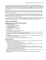
• For proper cooling, mount the controller 

vertically

, with the two screw mounting tabs at the bottom of the unit. It is not 

necessary to remove the covers before mounting.

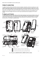
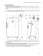
• Dimensions of the rear keyhole slot and lower mounting tabs are shown in Fig. 2, along with a step-by-step wall mounting 

procedure.

NOTE: Install one panhead screw (intended for the rear keyhole slot) into the wall first, then hang the controller on that screw. 

Then use screws in the two lower tabs to secure. See Fig. 2.

Fig. 2. WEB/CP-202-XPR or WEB/CP-602-XPR controller wall mounting dimensions in inches (mm) and details.

To mount unit on wall.

1.

For the rear center keyhole slot, install a pan head screw into the wall (

1a

 in Fig. 2). Do not tighten completely. Leave the 

back of the screw head about 3/32 in. (2.4mm) from the wall (

1b

 in Fig. 2).

2.

Position the unit over the screw (

2a

 in Fig. 2), entering the screw head into the keyhole slot in the back of the unit. 

3.

Pressing the unit against the wall, slide it down so the screw is captured by the slot (

2b

 in Fig. 2).

4.

Level the unit, and install a screw into each of the two lower mounting tabs (

3

 in Fig. 2).

7.75 (197)

39.4 (100)

2.125 (54)

12.03 (306)

0.59 (15)

2 x 
0.225 (5.7)

5.9 (150)

R. 0.1 (2.54)

0.433 (11)

0.41 (10.4)

M29987

1a

1b

2a

2b

3

3/32 (2.4)

10.16 (258)

Summary of Contents for WEB/CP-202-XPR

Page 1: ...4 MHz 128MB Flash 256MB DDR RAM Base unit including two Ethernet ports one RS 232 port one RS 485 port integral power supply for 24Vac dc input and 16 onboard I O points 8 universal inputs 4 digital outputs 4 analog outputs WEB CP 202 XPR GWa WEB CP 602 XPR GWb WEB CP 202 XPR or WEB CP 602 XPR with a factory installed wireless GPRS modem module and a SIM card for use on the Wyless Network These ar...

Page 2: ...unit allow cooling by air convection The front cover is split in two halves each secured by two screws where the right cover overlaps the left cover The right side provides access to all wiring terminals including controller communications ports I O point terminals and 24V power input terminals See Fig 1 for the location of important features Fig 1 Features of the WEB CP 202 XPR and WEB CP 602 XPR...

Page 3: ... Platforms WEB CP 202 XPR models PowerPC 405EP 250 MHz processor 128 MB SDRAM and 64 MB Serial Flash WEB CP 602 XPR models PowerPC 440 524 MHz processor 256 MB DDR RAM and 128 MB Serial Flash Real time clock Two 2 Ethernet ports 10 100 Mbps with RJ 45 connectors One 1 RS 232 port using an RJ 45 connector One 1 isolated RS 485 15 Vdc power on a 6 position connector Usable as a standard non powered ...

Page 4: ...ating temperature range 0 to 50 C 32 to 122 F Storage temperature range 0 to 70 C 32 to 158 F Relative humidity range 5 to 95 at 25 C 77 F non condensing Agency Listings UL 916 C UL listed to Canadian Standards Association CSA C22 2 No 205 M1983 Signal Equipment CE FCC part 15 Class A BTL B BC BACnet Building Controller listed when the BACnet driver is installed and configured PREPARATION Unpack t...

Page 5: ...aAX Nrio Guide NiagaraAX User Guide PRECAUTIONS This document uses the following warning and caution conventions CAUTION Cautions remind the reader to be careful They alert readers to situations where there is a chance that the reader might perform an action that cannot be undone might receive unexpected results or might lose data Cautions contain an explanation of why the action is potentially pr...

Page 6: ...must be secured to earth ground MOUNTING NOTE This product is intended for indoor use only The unit should not be exposed to ambient conditions outside of the range of 0 C 32 F to 50 C 122 F or relative humidity outside the range of 5 to 90 at 25 C 77 F non condensing Refer to the Environment section on page 4 for further details on storage specifications NOTE Before mounting the unit 1 Remove any...

Page 7: ... Fig 2 WEB CP 202 XPR or WEB CP 602 XPR controller wall mounting dimensions in inches mm and details To mount unit on wall 1 For the rear center keyhole slot install a pan head screw into the wall 1a in Fig 2 Do not tighten completely Leave the back of the screw head about 3 32 in 2 4mm from the wall 1b in Fig 2 2 Position the unit over the screw 2a in Fig 2 entering the screw head into the keyhol...

Page 8: ...he left cover Fig 3 Controller cover removal To remove the right cover 1 Using a 1 Phillips screwdriver remove the two screws in the right cover as shown in Fig 3 left Carefully set the screws aside to reuse 2 Slide the cover towards the right to disengage 3 Lift the right cover away from the unit and set aside Replace by simply reversing this procedure To remove the left cover 1 Remove the right ...

Page 9: ...move the appropriate knockouts as needed before mounting to the wall Note that the shielded 24V power input wiring area has a hole on the bottom side as well as an oval shaped knockout on the rear of the chassis If necessary install any conduit or cable clamps to knockout holes Locate and remove chassis knockouts 1 To remove a rear knockout a Hold the unit with its knockout side on flat work surfa...

Page 10: ...ype connector Inserting a SIM card and mounting the GPRS stub antenna 1 Remove both covers see Removing and Replacing the Covers on page 8 2 Locate the SIM card socket near the upper left corner of the controller above the LEDs Fig 5 3 Orient the SIM with its angled corner up foil connectors facing the socket writing side towards metal shield as shown in Fig 5 and slide down fully into the socket ...

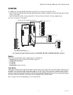
Page 11: ...K THERMISTOR 0 TO 10 VDC 4 TO 20 MA DRY CONTACTS PULSE CONTACTS ANALOG OUTPUTS 4 0 TO 10 VDC GND V UI4 UI3 UI2 UI1 GND UI8 UI7 UI6 UI5 GND GND V GND AO4 AO3 AO2 AO1 GND RS 232 COM1 RJ45 3C4 NO4 NO3 NO2 NO1 1C2 P P PB S TRIDIUM 2 6 SERIES OPTION CARD AREA INCLUDING SOCKET HEADER LEFT AND BLANKING PLATE RIGHT SEE ABOUT OPTION CARDS ON PAGE 12 LEDS 10 N GND L DIGITAL RELAY OUTPUTS 4 FORM A RELAY TYPE...

Page 12: ...rd must be removed at a later date Table 1 T x02 XPR 24 option cards Model Description Note NPB LON FTT 10A LON LonWorks adapter with a 2 position removable screw terminal connector plug Port operates in the hosted NiagaraAX station as LON1 NPB 2X RS485 Dual optically isolated RS 485 adapter with two 3 position removable screw terminal connector plugs Ports operate in the hosted NiagaraAX station ...

Page 13: ...ess as resource usage varies with each application database WIRING SUMMARY See Fig 6 on page 11 to locate connectors and other components on the controller Make connections to the controller in the following order 1 Install any option board LON RS 485 RS 232 in the available option slot See Installing an Option Card on page 12 for general procedures For complete details refer to the specific docum...

Page 14: ...e directly below the 3 position terminal block a Wire nearby earth ground to the G ground terminal using 14 AWG or larger wire b Wire 24V power to the N neutral and L line terminals 4 Replace the shield over the 3 position terminal block If wiring is through the back oval knockout install an end plug into the hole below the terminal block see Fig 7 right 5 Replace the right cover when finished wit...

Page 15: ...se Thermistor Inputs support 10K Thermistor temperature sensors Input accuracy is in the range of 1 of span By default conversion is for a standard Type 3 thermistor sensor with a sensor range of 10 to 135 F 23 3 to 57 2 C Using a conversion type of Tabular Thermistor you can specify a different thermistor response curve by importing a thermistor curve xml file Currently the kitIo module contains ...

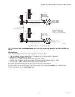
Page 16: ... accuracy is 2 of span without user calibration Fig 10 shows the wiring diagram for a 0 to 10 Vdc sensor Fig 10 0 to 10 Vdc sensor wiring diagram 4 to 20 mA Inputs support self powered or controller powered 4 to 20 mA sensors The input requires an external 499 ohm resistor for current input four resistors are supplied For controller powered sensors the controller s two V terminals supply 24 Vdc at...

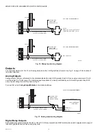
Page 17: ... 500ms Contacts must remain open at least 500ms and be closed at least 500ms Both types of dry contacts support 3 3 Vdc open circuits or 330 µA short circuit current Fig 12 on page 18 shows the wiring diagram For a pulse contact use the CounterInputPoint in the station database For other dry contacts use the BooleanInputPoint M28873 SHIELDED TWISTED CABLE 200 FEET 61 M MAXIMUM CUT AND TAPE SHIELD ...

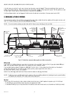
Page 18: ...13 Analog output wiring diagram Digital Relay Outputs Each digital relay output is rated at 24 Vac or Vdc at 0 5A Relay outputs have MOV metal oxide varistor suppressors to support inductive type loads such as heavy duty relay coils M28874 SHIELDED TWISTED CABLE 200 FEET 61 M MAXIMUM CUT AND TAPE SHIELD WIRE BACK AT DEVICE SHIELD USE POINT CounterInputPoint PULSE RANGE 20 Hz 50 DUTY CYCLE MINIMUM ...

Page 19: ... an additional NrioNetwork with a Port Name property of COM2 and Trunk property of 2 For more details see the NiagaraAX NRIO Guide For wiring details see Wiring to Remote I O Modules on page 23 Note that a maximum of three IO 16 REM H modules is recommended for a WEB CP 202 XPR due to platform resource considerations After remote I O modules are discovered and added to the station under this separ...

Page 20: ...g to a hub or Ethernet switch The controller s factory default IP address for PRI NET1 is 192 168 1 12n where the last numeral n in the address matches the last digit in the controllers s serial number and the subnet mask is 255 255 255 0 By default SEC NET2 on the unit is disabled Refer to the JACE NiagaraAX Install and Startup Guide for details on changing IP address NOTE Typically you only use ...

Page 21: ...in cable instead Note that flat silver satin cable is unshielded If installing this cable in a noisy electrical envi ronment run the cable through conduit 2 If you need a temporary serial shell connection from your PC to the controller and you have the necessary RJ 45 to DB 9 null modem adapter part number H10148 but you have no silver satin cable you can substitute an ordinary Ethernet patch cabl...

Page 22: ...OM2 is unavailable to NiagaraAX However note at the time of this document the released WEB CP 202 XPR controller does not include the onboard Jennic module EXTERNAL 12V BACKUP BATTERY The controller provides a 2 position connector for support of an external 12V sealed lead acid SLA type rechargeable battery part number 712BNP Usage is optional For more details see Backup Battery on page 25 Fig 16 ...

Page 23: ...up Batteries on page 24 PS PS BB RS 485 RS 485 485 GND PS PS BB PS PS BB PS PS BB S S S POWER SUPPLY 15V AND 12V BACKUP BATTERY IS WIRED TO REMOTE IO MODULES USING A 3 CONDUCTOR WITH SHIELD CABLE USE THE SHORTEST WIRING ROUTE POSSIBLE FOR POWER WIRING STAR TEE BUS AND LOOP TOPOLOGIES ARE ALL PERMISSIBLE USE STANDARD VOLTAGE DROP CALCULATIONS FOR DISTANCE AND WIRE GAGE TO ENSURE THAT VOLTAGE AT THE...

Page 24: ...e cover atop a metal shield plate see Fig 1 on page 2 This battery allows the controller to continue station operation only through very short power bumps meaning a few seconds in duration If a longer outage occurs the NiMH battery provides enough run time for the unit to backup data and then shutdown Typically this process takes about one minute Shutdown occurs automatically after data is backed ...

Page 25: ... batteries discharge in parallel However as the sealed lead acid backup battery capacity is much greater the NiMH battery pack discharges much slower than if these backup batteries were bad or not present NOTE If the backup battery test was bad upon loss of primary power the controller performs an immediate shutdown backing up data and powering off including expansion modules Replace the sealed le...

Page 26: ... controller models so equipped and is visible on the cover It flashes various LED patterns based on the state of the modem This LED is directly under control of the modem itself versus NiagaraAX software Upon initial power up the GPRS LED pattern is typically 600ms On and 600ms Off and may change depending on various modem state changes If the controller does not have the integral GPRS modem this ...

Page 27: ...ped Additionally NiMH batteries lose charge over time if not kept trickle charged for more details see NiMH battery pack on page 24 Therefore even a new unit or replacement battery will require up to 18 hours of powered operation before it can provide reliable backup power is at full charge The controller monitors the NiMH battery and periodically loads the battery to test its ability to maintain ...

Page 28: ...rews 9 Replace the covers 10 Restore power to the controller and verify normal operation Battery Disposal Please dispose of the used NiMH battery in accordance with local state and federal regulations WARNING Do not incinerate or mutilate the battery as this may cause it to burst or release toxic materials If regulations specify returning the old battery to a recycling center but no acceptable rec...

Page 29: ...ck to the controller Failure to do so may result in electrical shock or equipment damage CAUTION Before handling circuit boards discharge any accumulated static by touching a nearby grounded object For details see Static Discharge Precautions section on page 6 To replace a controller with a new replacement unit proceed as follows Replacing a controller 1 If possible use the appropriate NiagaraAX s...

Page 30: ...ng and place on a flat work surface 12 If applicable remove any option card installed in the old controller and install the card into the replacement controller See Installing an Option Card on page 12 for more details 13 Reroute the removed power communications and I O wiring through the knockouts and wiring holes in the replacement controller as done previously and position the unit in place on ...

Page 31: ...n a return authorization RMA number and other instructions Please provide Product model Serial number Nature of the defect Purchase order number to secure RMA United States Phone 804 254 7086 ext 11 E mail for RMA rma tridium com Return to Tridium Inc 2256 Dabney Road Suite C Richmond VA 23230 Attn Return Department RA ________ Asia Pacific Phone 65 6887 5154 Fax 65 6887 5342 Address Tridium Asia ...

Page 32: ...Regulations Cet appareil numerique de la classe A respecte toutes les exigencies du Reglement sur le material broilleur du Canada CE Declaration of Conformity PowerPC is a registered trademark of International Business Machines Corporation JACE and JAVA are registered trademark of Sun Microsystems Inc LON and LonWorks are registered trademarks of Echelon Corporation NiagaraAX and the Niagara logo ...

Reviews: