WEBVISION™
95-7769—01
70
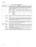
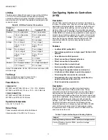
HYD Outputs fields
HYD Switching Levels
Purpose
To configure the Hydronic controller staged output switching
levels.
Mode
Configuration can be performed with the wizard Off-line or
On-line.
Procedure
1.
Click the
Switching Levels
button on the left pane to
open the
Switching Levels Configuration
page.
2.
Enter information into available fields.
3.
Click
Commit
to save the settings or
Reset
to revert to
the last saved settings.
4.
Click
Next
to display the
Zone Control Configuration
page or
Back
to display the
Equipment Control
Configuration
page.
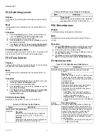
HYD Switching Levels fields
All levels can be set in the range 0% to 100%.
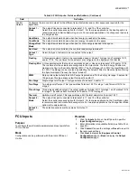
HYD Zone Control
Purpose
To configure the heating and cooling setpoints for the
Occupied, Standby, and Unoccupied operating modes.
Mode
Configuration can be performed with the wizard Off-line or
On-line.
Procedure
1.
Click the
Zone Control
button on the left pane to open
the
Zone Control Configuration
page.
2.
Enter information into available fields.
3.
Click
Commit
to save the settings or
Reset
to revert to
the last saved settings.
4.
Click
Next
to display the
Miscellaneous Configuration
page or
Back
to display the
Switching Levels
Configuration
page.
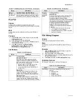
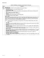
HYD Zone Control fields
Setpoints can range from 10 to 35 ºC (50 to 95 ºF).
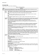
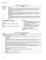
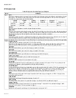
Table 45. Hydronic Controller Outputs Fields.
Name
Definition
Output
Options
Defines the operating characteristics of the two valve actuator outputs, Output 1 and Output 2 as configured in the
Outputs tab. The settings for both Outputs have the same meaning as described in the following text.
Valve Direction
Define the operating direction of the valves for actuator types Floating, PWM, and Thermal.
DIRECT
To open, the valve is modulated from 0% to 100%.
REVERSE
To open, the valve is modulated from 100% to 0%.
Min Stage Off Time
Define the minimum off-time for control outputs configured for operation as staged outputs. This setting is particularly
useful for heat exchanger operation or compressor units. Each stage of the controlled output stays off for the minimum
period of time before the controller turns it on again. The selectable range is 0 to 600 seconds.
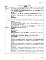
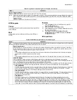
Min St On or PWM Per or Valve Runtime
This configuration parameter has three different functions depending on the control output type selected in Control
Outputs:
(CONTROL OUTPUT TYPE = FLOATING)
The value is the actuator run-time in the range 20 to 600 seconds.
(CONTROL OUTPUT TYPE = PWM)
The value is the cycle period of the PWM output in the range 20 to 600 seconds.
(CONTROL OUTPUT TYPE = ONE, TWO OR THREE STAGE)
The value is the minimum on-time for each of the stages, for controlling compressor units.
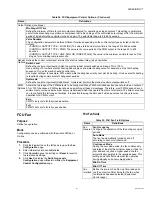
PWM
Options
Configures the full range of the PWM outputs. For many PWM-controlled devices, an output of 0% or 100% is not
allowed since a PWM output shows no switching at these percentages. Therefore, most PWM devices have a minimum
duty cycle and a maximum duty cycle between which they operate from zero to full scale. The fields here configure the
full range settings. You can swap the Zero and Full range values to achieve reverse operation for a PWM output.
ZERO
PWM % duty cycle for fully closed position.
FULL
PWM % duty cycle for fully open position.

