
WT8840 TRADE WATER HEATER CONTROLS
34-00013EF—01
2
PLANNING THE INSTALLATION
WARNING
Fire or Explosion Hazard.
Can cause severe injury, death or property
damage.
Follow these warnings exactly:
1. Plan the installation as outlined below
2. Plan for frequent maintenance as
described in the Maintenance section.
3. Review the following conditions that can
apply to your specific installation and take
the precautionary steps provided.
Frequent Cycling
This control is designed for use on appliances that
typically cycle three to five times a day. In year-round
applications with greater cycling rates of 10,000
cycles annually, the control can wear out more quickly.
Perform a monthly checkout.
Water or Steam Cleaning
If a control gets submerged in water, replace it. If the
appliance is likely to be cleaned with water or steam,
protect (cover) the control and wiring from water or
steam flow. Mount the control high enough above the
bottom of the cabinet so it does not get wet during
normal cleaning procedures.
High Humidity or Dripping Water
Dripping water can cause the control to fail. Never
install an appliance where water can drip on the
control. In addition, high ambient humidity can cause
the control to corrode and fail. If the appliance is in a
humid atmosphere, make sure air circulation around
the control is adequate to prevent condensation. Also,
regularly check out the system.
Corrosive Chemicals
Corrosive chemicals can attack the control, eventually
causing a failure. If chemicals are used for routine
cleaning, avoid contact with the control. Where
chemicals are suspended in air, as in some industrial
or agricultural applications, protect the control with a
cover.
Dust or Grease Accumulation
Heavy accumulations of dust or grease can cause the
control to malfunction. Where dust or grease can be a
problem, provide covers for the control to limit
contamination.
Heat
Excessively high temperature can damage the control.
Make sure the maximum ambient temperature at the
control does not exceed the rating of the control. If the
appliance operates at very high temperatures, use
insulation, shielding, and air circulation, as necessary,
to protect the control. Proper insulation or shielding
should be provided by the appliance manufacturer.
Verify proper air circulation is maintained when the
appliance is installed.
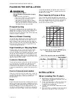
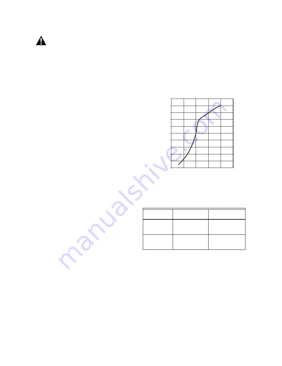
Flow Capacity & Pressure Drop
Fig. 1 shows the typical flow (kBTU/hr) vs pressure
drop (in. w.c.) curve for natural gas and LP gas. Actual
pressure drop depends on the internal configuration
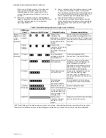
of the valve. Table 1 shows the pressure drop at
various flows for the control.
Fig. 1. Typical capacity curve for WT8840 family
water heater control system.
Table 1. Gas capacity conversion for WT8840.
INSTALLATION
When Installing This Product…
1.
Read these instructions carefully. Failure to
follow them could damage the product or cause
a hazardous condition.
2.
Check the ratings given in the instructions and
on the product to make sure the product is
suitable for your application.
3.
Installer must be a trained, experienced service
technician.
4.
After installation is complete, check out product
operation as provided in these instructions.
Gas Type
Flow (kBTU/hr)
Pressure Drop
(in. w.c.)
NG
30
50
75
1.43
1.47
1.54
LP
30
50
75
0.91
0.94
0.97
M36122
0.8
0.9
1.0
1.1
1.2
1.3
WT8840 CAPACITY DATA
0
10
20
30
40
50
60
70
80
90
100
PRESSURE DROP (IN WC)
FLOW
(KBTU/HR)


