HONEYWELL MODEL 700/800 SIGNAL PROCESSOR AND VIEWING HEAD
13
66-2069EP—04
new setting, press the STORE button until “--” is shown,
indicating the value has been accepted.
If no activity occurs for a period of four seconds while the
menu value is displayed, it will revert back to the operating
display.
To exit a menu at any time without saving changes, simply
press the RESET/rE button.
The following describes the functions of the LED indicators,
display and push buttons:
Front Panel LED Indicators and Display
• ON SEQ/AUTO SET LED (green):
— Used in conjunction with the BNR-ON SEQ START/
END and BNR-OFF SEQ START/END buttons during
the automatic setup process
• OFF SEQ/FAULT LED (green):
— Used in conjunction with the BNR-ON SEQ START/
END and BNR-OFF SEQ START/END buttons during
the automatic setup process
— Indicates a fault condition
• Two digit display
— When in operating mode, the display indicates the
current flame signal, which ranges between 00 and 29
— Upon power up, indicates whether an IR or UV viewing
head is attached and the selected gain setting; such
as r7 (IR with gain of 7) or u5 (UV with gain of 5).
— Indicates various characters during the automatic
setup process as well as whether the panel is locked
• FLAME SIG LED (yellow):
— When a flame is present, LED flashes at a rate
proportional to flame signal, except when the pulses
are interrupted once per second for viewing head self-
checks.
• FLAME ON LED (red):
— When the flame signal is above the selected value, the
LED will be illuminated and the flame relay will be
energized.
Push Button Functions
• RELAY ON SETPOINT button:
— Allows user to select flame on threshold value. When
the flame signal is above the selected value, the flame
relay will be energized. Used in conjunction with the
INCREASE, DECREASE and STORE buttons (range
of 00 to 29).
• LOAD FACTORY DEFAULTS button:
— Used to restore all settings to the factory default
values
•
↑
INCREASE button:
— Used to increase parameter value when in
programming mode
• RATIO (%) RELAY OFF/RELAY ON button:
— Used along with the INCREASE, DECREASE and
STORE buttons to set the RELAY OFF setpoint at a
percentage of the RELAY ON setpoint. Adjustable
from 20% to 80%.
• STORE button:
— Stores new parameter values during programming
— After making changes “--” will be displayed indicating
the new values are accepted and stored
•
↓
DECREASE button:
— Used to decrease parameter value when in
programming mode
• BNR-ON SEQ START/END button:
— Used to initiate and proceed through the automatic
parameter setup sequence, which includes the RELAY
ON, RATIO (%) and GAIN settings (the FFRT, mA
output and communication address must be set
manually)
• BNR-OFF SEQ START/END button:
— Used during the automatic parameter setup sequence
• ACCEPT RATIO/SET GAIN button:
— Allows user to set the viewing head gain in conjunction
with the INCREASE, DECREASE and STORE buttons
— Used in conjunction with the BNR-ON SEQ START/
END and BNR-OFF SEQ START/END buttons during
the automatic setup process
• FFRT 1/2/3 SEC OPTION button:
— Used to set the FFRT timing along with the
INCREASE, DECREASE and STORE buttons
• 0-20MA 4-20MA OPTION button:
— Used in conjunction with the INCREASE, DECREASE
and STORE buttons to select the proportional mA
output for the flame signal
• RESET rE button:
— Resets a lockout condition
— Also used to exit a menu while programming
— Used to set the Modbus address along with the
INCREASE, DECREASE and STORE buttons
Manual Setup of Setpoints
The keypad of the signal processor is used to set the IR/UV
GAIN, RELAY ON, RATIO % (Relay Off), FFRT and mA output
option setpoints. The following section describes this process.
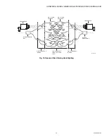
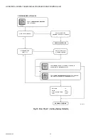
Also refer to Fig. 23, 24, 25, 26 and 27.
Setting the Viewing Head Gain
The gain of the IR and UV viewing heads can be adjusted. In
addition to the information in this section, refer to Fig. 27. At
power-up, the 700 signal processors display codes to tell the
operator what type of viewing head and what gain is being
used. Default values are “r5” for the IR viewing head and “u5”
for the UV viewing head. The “r” or “u” denote IR or UV
viewing heads, respectively, while the numeric digit indicates
the current gain setting. The gain can be adjusted from 1 to 9
with a gain of 5 being the factory default gain.
To change the gain, press and hold the SET GAIN button for
two seconds until the current value is displayed. Use the
INCREASE and DECREASE buttons to change the setting as
appropriate while the value is displayed. To store the new
setting, press the STORE button until “- -” is shown, indicating
the value has been accepted.
If no activity occurs for a period of four seconds while the
value is displayed, the display will return to the operation
mode without saving the new setpoint.
To exit the menu at any time without saving changes, simply
press the RESET/rE button.
The gain is live; changes are effective immediately, but if the
displayed gain value is not stored (by pressing STORE), and
no other buttons are pressed, the processor returns to the
previous setting after four seconds.
Relay On Setpoint

