background image

PROCESSADOR DE SINAL E SENSOR DE CHAMA HONEYWELL MODELO 700/800

23

66-2069EP—04


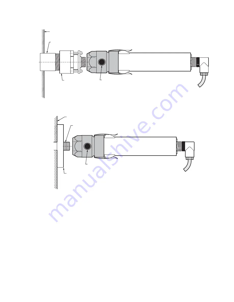
Fig. 14. Exemplo de Montagem do Sensor de Chama. 


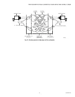
Fig. 15. Exemplo de Montagem do Sensor de Chama. 

Exemplos de montagem

Ar de purga deve ser fornecido por meio da conexão de ar de 

purga para reduzir o calor por condução e para manter o tubo 

de visualização e a lente do sensor de chama livres de sujeira 

e detritos. Consulte "Ar de Purga" na página 8 para requisitos. 

Por razões de isolamento elétrico, a linha de ar de purga deve 

ser instalada usando um material isolante, como uma 

mangueira de borracha, entre a linha de ar de purga e o 

sensor de chama. Observe que um tubo extensor pode ser 

necessário para posicionar o sensor de chama além da placa 

frontal do queimador para evitar altas temperaturas. Além 

disso, uma base de montagem de Ultem para isolamento 

térmico está disponível para substituição para todos os 

modelos, que está classificado para serviço contínuo a 160°C 

(320°F). Também estão disponíveis camisa de refrigeração 

que são utilizadas com refrigeradores de vórtex. O niple R-

518-13, o adaptador acoplador de trava R-518-PT13/R-518-

PT13L ou o acoplador de trava R-518-CL13-HTG Ultem 

Honeywell também pode ser utilizado para isolamento de 

calor. Consulte a seção Acessórios deste documento para 

obter números de peças de acessórios. 

NIPLE TOE 1 (25) NPT 

RÓTULA DE AJUSTE 700-1

PLACA FRONTAL DO QUEIMADOR

MP34537

CONEXÃO AR DE PURGA 1/4 (6) NPT 

SENSOR DE CHAMA S70X

CONEXÃO DE RÁPIDO 

DESENGATE 

(FORNECIDO) 

MP34538

CONEXÃO AR DE 

PURGA 1/4 (6) NPT 

SENSOR DE CHAMA S70X

CONEXÃO DE RÁPIDO 

DESENGATE 

(FORNECIDO) 

PLACA FRONTAL DO QUEIMADOR 

OU JANELA DE VISUALIZAÇÃO 

TUBO 1/2 (13) NPTM

FLANGE 

(OPCIONAL) 

Summary of Contents for XL 800 Series

Page 1: ...mmunication connections are made through modular phone jacks located at the top of the signal processors Fig 9 Both signal processor models mount on a standard 35 mm DIN rail They snap into place and may be released from the rail using a flat screwdriver There are two types of viewing heads IR flicker sensitive and UV sensitive with various features offered resulting in ten different models See Ta...

Page 2: ...igh Pass Filter Pickup 33 Hz standard IR Optical Angle of View 1 degree 1 45 in dia at 6 ft or 3 7 cm dia at 1 8 m UV Detector Spec S706 S706PF S806 UVtron with spectral response 185nm to 260nm and a peak response at 210nm UV Optical Angle of View 5 degrees 1 inch per foot Cable Connectors S70X S80X Viewing Heads New installations highest level of EMI shielding available ASY785 50 foot C330S cable...

Page 3: ...released from the rail using a flat screwdriver Grounding and Shielding NOTE Installer must be a trained experienced flame safeguard service technician and should be familiar with the equipment operation and limitations and be aware of any applicable local codes and regulations 1 Connect a safety ground to the viewing head housing if applicable A ground screw is provided on the exterior of s70x s8...

Page 4: ...tical component failure occurrence system response will be to de energize the self check relay which in turn de energizes the flame relay Some of the internal power wiring of the Model 700ACSP and Model 700DCSP signal processors is shown in Fig 1 and Fig 2 Rectifier diodes separate the battery backup input from the main power bus until the battery voltage exceeds the internal DC voltage plus a dio...

Page 5: ...66 2069EP 04 Fig 1 Model 700ACSP Signal Processor Wiring APPROVED AC IN GROUND TO VIEWING HEAD 24 V BACKUP BATTERY OPTIONAL 0 20 OR 4 20 MA FOR INDICATOR OR INSTRUMENTATION 360 OHMS MAX CHASSIS EARTH OR SYSTEM GND M34280A 26VDC GND 125 A 4A 2A AC POWER SUPPLY t ...

Page 6: ...69EP 04 6 Fig 2 Model 700DCSP Signal Processor Wiring 26VDC GND 4A 1A 1A 125 A LIM M34282A APPROVED 24 V BACKUP BATTERY OPTIONAL 0 20 OR 4 20 MA FOR INDICATOR OR INSTRUMENTATION 360 OHMS MAX CHASSIS EARTH OR SYSTEM GND DC POWER SUPPLY 250 MA 26 PWR TO VIEWING HEAD ...

Page 7: ...r ITC CIC approved cable in metal conduit must be used between the S70x S80x and Signal Processor Pre assembled connector cable assemblies are listed below that provide the proper seal at the viewing head and meet ITC CIC approvals A field wire able connector that provides a proper seal at the viewing head along with ITC CIC rated raw cable are also available and listed below The cable installatio...

Page 8: ...Preparation of the C330S cable at the signal processor should be done as follows 1 Referring to Fig 5 strip cable 2 inches back to expose the braided shield 2 Pull braided and foil shield back so that only drain wire is at 2 inch length Trim the foil and braid shields at the cable jacket 3 Insulate the drain wire with heat shrink 4 Strip other wires as shown in Fig 5 WHITE BLACK RED GREEN TERMINAL...

Page 9: ...s from the hazardous location to the non hazardous location in order to keep potentially hazardous gases from being conducted into the non hazardous area Viewing Head Connector LED Indicators The viewing head connector has orange and green LEDs which can be viewed from the rear of the connector when the connector cover is removed The green LED displays the pulses out of the viewing head and the or...

Page 10: ... factory for assistance with fiber optic selection and pricing Purge Air Use a flexible air supply line to allow for repositioning of the viewing head and sight pipe until a final and permanent position has been decided A continuous flow of air must be maintained in order to reduce the conducted heat and to keep the sight pipe and viewing head lens free of dirt and debris Air required is about 5 S...

Page 11: ...ING adapter is used Vortex coolers M3204 M3208 M3210 M4025 Used with air cooling canister Contact your distributor or the factory for selection assistance Cable restraints 800CR 700CRLT Liquid tight S80X and S70X cable restraint versions The 800CR includes the 700CRLT and the 800ACC RING adapter S80X adapter ring 800ACC RING Adapter ring to fit S80X viewing heads to 700ACC cooling jacket and 700CR...

Page 12: ...e setpoints are adjusted Adjustment can be made easier by a 1 2 in swivel joint which Honeywell can supply if one is not available refer to Accessories on page 11 While the burner is firing vary the viewing angle while observing the green LED on the connector at the rear of the viewing head Adjust the viewing angle for the maximum pulse rate then lock the swivel joint to preserve this mechanical s...

Page 13: ...SEQ START END button Used to initiate and proceed through the automatic parameter setup sequence which includes the RELAY ON RATIO and GAIN settings the FFRT mA output and communication address must be set manually BNR OFF SEQ START END button Used during the automatic parameter setup sequence ACCEPT RATIO SET GAIN button Allows user to set the viewing head gain in conjunction with the INCREASE DE...

Page 14: ...at any time without saving changes simply press the RESET rE button Setting FFRT Flame Failure Response Time To access the FFRT setpoint press and hold the FFRT 1 2 3 SEC OPTION button for 2 seconds until the current value is displayed Refer to Fig 25 for the setup flowchart The FFRT can be set at 1 2 or 3 seconds While the value is displayed adjustments may be made via the INCREASE or DECREASE ar...

Page 15: ... alternate between UA and 93 RESET must be pressed to clear this the old values for RELA Y ON and RA TIO will remain in effect The values can be worse than just unacceptable If the flame relay de energizes while reading BNR ON values the display will show bo and data taking will be aborted Other faults such as a BNR ON flame signal that is too low to use or BNR OFF readings that are too close to t...

Page 16: ...ress up arrow to change setting from P0 to P1 3 Press STORE The factory default Modbus address of the 700ACSP and 700DCSP is 0 and must be changed to a number between 1 and 32 to establish communication between the signal processor and the host control When more than one signal processor is in the network ensure that each signal processor has a unique Modbus address within the range of 1 to 32 Mod...

Page 17: ...dd 0 1 40087 ADDRESS Modbus address used by RS 485 and IRDA read write Each device must have a unique address 0 247 40089 PROTOCOL Protocol read write 0 Honeywell protocol 1 Modbus protocol 0 1 Table 4 MODBUS registers map Continued Register Name Description Minimum Maximum BNR 1 11 BOILER 1 ADDRESS M34457 NOTES A CONVERTER MAY BE NECESSARY FOR COMMUNICATION WITH THE MODBUS MASTER CONTROL MODBUS M...

Page 18: ...S FOR RS 422 COMMUNICATION PER THE VENDOR S INSTRUCTION SHEET RJ11 CONNECTOR IS CUSTOMER SUPPLIED AND WIRED SOFTWARE DRIVERS MAY BE DOWNLOADED FROM B B ELECTRONICS WEBSITE RJ11 MODULAR CONNECTOR 1 2 3 4 5 6 COLOR TYPE A WHI BLK RED GRN YEL BLU COLOR TYPE B BLU YEL GRN RED BLK WHI CONVERTER CONNECTOR NC RDA RDB TDA TDB GND DESCRIPTION NC FROM PROCESSOR FROM PROCESSOR TO PROCESSOR TO PROCESSOR GROUN...

Page 19: ...ble Read Only Memory in the signal processors This data is then error checked when it is read at power up If the data does not match exactly what was previously stored the signal processor discards all data displays EE and loads factory defaults The RELAY ON SETPOINT is set to 31 Since the flame count cannot go this high the flame relay cannot be energized The signal processor can be reset by chan...

Page 20: ...d S806 Viewing Heads HEX 1 1 2 38 ACROSS FLATS 8 1 4 210 6 13 32 163 5 16 8 1 27 64 36 1 3 4 45 DIA MOUNTING BLOCK 1 4 NPT FOR PURGE AIR 1 2 NPT FOR SIGHTING PIPE M34283B 1 1 2 38 7 11 16 195 6 153 1 1 2 38 M34284B HEX 1 1 2 38 ACROSS FLATS 1 3 4 45 DIA MOUNTING BLOCK 1 4 NPT FOR PURGE AIR 1 2 NPT FOR SIGHTING PIPE 13 32 10 1 1 8 29 DIA ...

Page 21: ...0 800 SIGNAL PROCESSOR AND VIEWING HEAD 21 66 2069EP 04 Fig 12 Model 700DCSP Signal Processor APPROVED M34584A 26 PWR 5 1 2 139 2 29 32 74 3 1 4 83 1 4 6 35MM DIN RAIL DIN RAIL RELEASE C L RS 422 WIRING RELAY CONNECTIONS ...

Page 22: ...00 SIGNAL PROCESSOR AND VIEWING HEAD 66 2069EP 04 22 Fig 13 Model 700ACSP Signal Processor APPROVED M34851A 5 1 2 139 2 29 32 74 MODEL 700AC 3 1 4 83 1 4 6 35MM DIN RAIL DIN RAIL RELEASE C L RS 422 WIRING RELAY CONNECTIONS ...

Page 23: ...er from the burner front plate to avoid high temperatures Additionally an Ultem replacement insulating mounting block is available for all models which is rated for 320F 160C continuous service Also available are cooling jackets which are used with vortex coolers The Honeywell Ultem R 518 13 nipple or R 518 PT13 R 518 PT13L locking coupler adapter and R 518 CL13 HTG locking coupler can also be use...

Page 24: ...cation Fig 17 UV Viewing Head Location DETECTOR IN GOOD SIGHTING POSITION PARALLEL SIGHTING BURNER NOZZLE CENTERLINE DETECTOR IN POOR SIGHTING POSITION LOW FREQUENCY FLICKER ZONE HIGH FREQUENCY FLICKER ZONE M33285B UV VIEWING HEAD SIGHTED ON UV ZONE BURNER NOZZLE CENTERLINE UV RADIATION ZONE M33286B ...

Page 25: ...HEAD 25 66 2069EP 04 Fig 18 Opposed Fired Viewing Head Sighting VIEWING HEAD BURNER NOZZLE NO 1 NO 1 FLAME ENVELOPE NO 2 FLAME ENVELOPE VIEWING HEAD BURNER NOZZLE NO 2 HIGH FREQUENCY IR ZONE LOW FREQUENCY ZONE LESS THAN 36HZ HIGH FREQUENCY IR ZONE M33287B ...

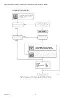
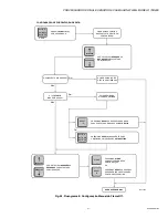
Page 26: ... AUTO SET LIGHT LIT DISPLAY SHOWS PL MEANING THE PANEL IS LOCKED DISPLAY SHOWS CF MEANING CONFIRM RELAY ON 16 RATIO 50 0 20 4 20mA OPTION 4 20mA FFRT 1 SEC NORMAL OPERATION N RESTORING DEFAULT VALUES Y N Y OR M34456A PRESS RESET OR WAIT 4 SECONDS TO CANCEL CHANGING THE AUTO SET VALUES RESET rE PRESS LOAD FACTORY DEFAULTS AGAIN TO CONFIRM YOU WANT TO CHANGE THE AUTO SET VALUES LOAD FACTORY DEFAULTS...

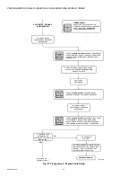
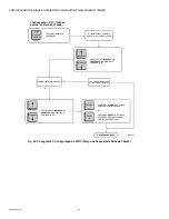
Page 27: ...AY SHOWS PL UNTIL KEY RELEASED DISPLAY SHOWS CF MEANING CONFIRM DISPLAY SHOWS BO MEANING BURNER OFF NORMAL OPERATION N AUTO SETUP Y N N Y Y OR M34458B PRESS RESET OR WAIT 4 SECONDS TO CANCEL AUTO SETUP RESET rE PRESS RESET TO CANCEL AUTO SETUP RESET rE PRESS BNR ON SEQ AGAIN TO CONFIRM YOU WANT TO BEGIN TAKING DATA FOR AUTO SETUP BNR ON SEQ START END BNR ON SEQ START END PRESS BNR ON SEQ FOR 2 SEC...

Page 28: ...UES ARE SAVED DISPLAY RETURNS TO CURRENT FLAME SIGNAL AND AUTO SETUP OFF SEQ LIGHT FLASHES NORMAL OPERATION AUTO SETUP PAGE 2 CONTINUED N Y M34459A NOTE PRESS RESET AT ANY TIME DURING THIS PROCEDURE TO CANCEL AUTO SETUP RESET rE PRESS BNR OFF SEQ AGAIN TO END TAKING BURNER OFF DATA OR WAIT UNTIL THE COUNT REACHES ZERO 15 SECONDS MINIMUM RECOMMENDED BNR OFF SEQ START END PRESS BNR ON SEQ AGAIN TO E...

Page 29: ... 81 RATIO IS UNACCEPTABLE RATIO MAY BE ACCEPTABLE DISPLAY ALTERNATES SHOWING AC AND THE NEW RATIO SETTING NORMAL OPERATION NORMAL OPERATION Y N Y M34460A AUTO SETUP PAGE 3 CONTINUED NOTE PRESS RESET AT ANY TIME DURING THIS PROCEDURE TO CANCEL AUTO SETUP RESET rE PRESS RESET TO CANCEL AUTO SETUP RESET rE DISPLAY SHOWS _ _ FOR ONE SECOND AND NEW VALUES ARE SAVED PRESS ACCEPT RATIO SET GAIN TO ACCEPT...

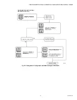
Page 30: ...LAY SHOWS PL UNTIL KEY RELEASED NORMAL OPERATION N SETTING RELAY ON VALUE Y N Y OR M34461A PRESS RESET OR WAIT 4 SECONDS TO CANCEL CHANGING THE AUTO SETTING RESET rE USE INCREASE OR DECREASE KEYS TO ADJUST SETTING INCREASE DECREASE USE INCREASE OR DECREASE KEYS TO ADJUST SETTING INCREASE DECREASE PRESS RESET OR WAIT 4 SECONDS TO RESTORE OLD SETTING OR PRESS STORE TO SAVE THE NEW SETTING STORE RESE...

Page 31: ...ETTING RATIO PERCENTAGE Y N Y OR M34462A PRESS RESET OR WAIT 4 SECONDS TO CANCEL CHANGING THE AUTO RATIO RESET rE USE INCREASE OR DECREASE KEYS TO ADJUST SETTING INCREASE DECREASE USE INCREASE OR DECREASE KEYS TO ADJUST SETTING INCREASE DECREASE PRESS RESET OR WAIT 4 SECONDS TO RESTORE OLD SETTING OR PRESS STORE TO SAVE THE NEW SETTING STORE RESET rE RATIO RATIO OFF RATIO ON PRESS RATIO FOR 2 SECO...

Page 32: ...ONDS 2 SECS DISPLAY SHOWS CURRENT SETTING IN SECONDS DISPLAY SHOWS PL UNTIL KEY RELEASED NORMAL OPERATION N SETTING FLAME FAILURE RESPONSE TIME FFRT Y M34463A USE INCREASE OR DECREASE KEYS TO ADJUST SETTING INCREASE DECREASE USE INCREASE OR DECREASE KEYS TO ADJUST SETTING INCREASE DECREASE PRESS RESET OR WAIT 4 SECONDS TO RESTORE OLD SETTING OR PRESS STORE TO SAVE THE NEW SETTING STORE RESET rE ...

Page 33: ...ECONDS 2 SECS DISPLAY SHOWS 02 FOR 0 20 mA 42 FOR 4 20 mA DISPLAY SHOWS PL UNTIL KEY RELEASED NORMAL OPERATION N SETTING ANALOG OUTPUT LEVELS 0 20 4 20 mA Y M34464A USE INCREASE OR DECREASE KEYS TO ADJUST SETTING INCREASE DECREASE USE INCREASE OR DECREASE KEYS TO ADJUST SETTING INCREASE DECREASE PRESS RESET OR WAIT 4 SECONDS TO RESTORE OLD SETTING OR PRESS STORE TO SAVE THE NEW SETTING STORE RESET...

Page 34: ...CURRENT GAIN SETTING DISPLAY SHOWS PL UNTIL KEY RELEASED NORMAL OPERATION N SETTING VIEWING HEAD GAIN Y M34465A USE INCREASE OR DECREASE KEYS TO ADJUST SETTING INCREASE DECREASE PRESS RESET OR WAIT 4 SECONDS TO RESTORE OLD SETTING OR PRESS STORE TO SAVE THE NEW SETTING STORE RESET rE ACCEPT RATIO SET GAIN PRESS ACCEPT RATIO SET GAIN FOR 2 SECONDS 2 SECS ...

Page 35: ...e required safety functions required to achieve or maintain a safe state and is intended to achieve on its own or with other systems the necessary safety integrity for the required safety functions Safety Function Defined function which is performed by a safety related system with the aim of achieving or maintaining a safe state for the plant in respect of a specified hazardous event Proof Test Pe...

Page 36: ...l Each relay must be driven by an alternating signal of the proper frequency and duty cycle from the processor 700AC or 700DC Signal Processor Proof Test Interval The Proof test must be conducted every 1 to 5 years This range is given to allow for the test to be performed during the normally scheduled burner shutdown period It is the responsibility of the user to perform the proof test in the spec...

Page 37: ...nuity between SC COM and SC ON 3 Use a light source to generate a flame on condition and using a multimeter ensure continuity between RF A COM and RF A ON and between RF B COM and RF B ON 4 Remove any light source to generate a flame off condition and using a multimeter ensure continuity between RF A COM and RF A OFF and between RF B COM and RF B OFF after the FFRT Flame Failure Response Time has ...

Page 38: ...taining a safe state for the plant in respect of a specified hazardous event Proof Test Periodic test performed to detect failures in a safety related system so that if necessary the system can be restored to an as new condition or as close as practical to this condition MTTR Mean Time to Restoration The average duration required for restoration of operations after a failure λsd Rate of safe detec...

Page 39: ...06 S802 or S806 viewing head under test is correctly connected to a compatible signal processor 2 While performing the proof test disconnect or disregard the signal processor outputs so that any outputs due to testing do not affect the overall safety system and potentially cause a hazardous situation 3 Record all previously entered user programmable settings so that you can restore them to their d...

Page 40: ...oneywell Thermal Solutions HTS 1250 West Sam Houston Parkway South Houston TX 77042 ThermalSolutions honeywell U S Registered Trademark 2017 Honeywell International Inc 66 2069EP 04 M S Rev 02 17 Printed in United States a Increase the gain and store the setting Ensure the flamecount increased b Decrease the gain and store the setting Ensure the flamecount decreased 5 Restore all original settings...

Page 41: ... A única diferença entre os dois é que um aceita alimentação CA e o outro aceita CC Ambos modelos aceitam backup de alimentação de 24 V CC A maioria das conexões dos processadores de sinal é feita por meio de conectores Phoenix Conexões de comunicação são feitas por meio de portas modulares de telefone localizadas na parte superior dos processadores de sinal Fig 9 Ambos modelos de processador de s...

Page 42: ...a 1710nm 1 2 ponto de intensidade e resposta espectral máxima em 1400nm Filtro Passa Alto Padrão 33Hz Ótica IR Ângulo Visual 1 grau 1 45 pol diâm a 6 pés ou 3 7cm diâm a 1 8m Especificações do Detector IR S706 e S706PF S806 UVtron com resposta espectral de 185nm a 260nm e valor máximo a 210nm Ótica UV Ângulo Visual 5 graus 1 pol por pé Cabos Conectores Sensores de Chama S70X S80X Novas instalações...

Page 43: ...utos são apropriados para a sua aplicação 3 O instalador precisa ser um técnico treinado e experiente em proteção de chamas 4 Após o término da instalação verifique a operação do produto fornecida nessas instalações Montagem do Processador de Sinais Os processadores de sinal 700ACSP e 700DCSP podem ser montados em um trilho DIN 35mm padrão Eles encaixam no trilho e podem ser liberados com uma chav...

Page 44: ...ndentemente se o relé de chama é energizado ou não Internamente o relé da chama é ligado em série com o relé de autodiagnóstico não mostrado impedindo que o relé de chama seja energizado se o relé de autodiagnóstico não estiver energizado Circuitos exclusivos à prova de falhas para os relés de autodiagnóstico e de chama garantem que em caso de qualquer falha de um componente crítico a resposta do ...

Page 45: ... Fig 1 Montagem Elétrica do Processador de Sinal Modelo 700ACSP APPROVED AC IN TERRA PARA SENSOR DE CHAMA BATERIA DE BACKUP 24 V OPCIONAL 0 20 OU 4 20 MA PARA INDICADOR OR INSTRUMENTAÇÃO 360 OHMS MAX CHASSIS TERRA OU GND DO SISTEMA MP34280 26VDC GND 125 A 4A 2A AC POWER SUPPLY t ...

Page 46: ...g 2 Montagem Elétrica do Processador de Sinal Modelo 700DCSP 26VDC GND 4A 1A 1A 125 A LIM MP34282 APPROVED BATERIA DE BACKUP 24 V OPCIONAL 0 20 OU 4 20 MA PARA INDICADOR OU INSTRUMENTAÇÃO 360 OHMS MÁX CHASSIS TERRA OU GND DO SISTEMA ALIMENTAÇÃO CC 250 MA 26 PWR PARA SENSOR DE CHAMA ...

Page 47: ...x e o Processador de Sinal Os conjuntos de cabo conector pré montado que são relacionados abaixo fornecem o lacre adequado no sensor de chama e atendem às aprovações de ITC CIC Um conector montável que fornece um lacre adequado no sensor de chama juntamente com cabo classificado ITC CIC também estão disponíveis e relacionados abaixo A instalação do cabo precisa estar em conformidade com a versão m...

Page 48: ...aração do cabo C300S no processador de sinal deve ser da seguinte maneira 1 Com relação à Fig 5 desencape 2 pol de cabo para expor a blindagem trançada 2 Puxe o trançado e a malha de blindagem para trás para que apenas o fio de drenagem esteja com 2 polegadas de comprimento Corte a malha e o trançado de blindagem no revestimento do cabo 3 Isole o fio de drenagem com isolante termo retrátil BRANCO ...

Page 49: ...r de Chama ASY786 com o C330S Protegendo o Cabo do Sensor de Chama Séries de Conectores Note que quando a montagem elétrica precisa atender aos requisitos Classe I Divisão 2 para uso em locais perigosos e quando conduíte é usado o conduíte deve ser selado onde o cabo passa do local perigoso para o local não perigoso para manter gases potencialmente perigosos isolados da área não perigosa Indicador...

Page 50: ...o contínuo de 160 C 320 F bem como um niple Ultem NPTM de 1 2 pol número de peça R 518 13 ou um adaptador acoplador de trava de Ultem R 518 PT13 ou R 518 PT13L para reduzir o calor conduzido porém a radiação direta pode fazer com que a temperatura do invólucro ultrapasse esses limites Se o calor ambiente radiação direta é excessivo então um recipiente de resfriamento com refrigerador de vórtex ou ...

Page 51: ...s Acessórios apropriados devem ser usados para adaptar as conexões de processo de sensor de chama NPTF de 1 2 pol Acopladores de isolamento com trava R 518 PT13 e R 518 PT13L Adaptadores NPTM Ultem de 1 2 pol isolam o sensor de chama elétrica e termicamente e são usados em conjunto com o acoplador com trava R 518 CL13 HTG O R 518 PT13L possui lentes de quartzo Acoplador com trava R 518 CL13 HTG Us...

Page 52: ...sores de chama UV funcionarão bem em chamas de gás natural e óleo leve A posição de observação das chamas de óleo e de gás deve ser paralela ao eixo do queimador e apontado para a raiz da chama assim como com o detector de IR Consulte a seção anterior Detector IR A intensidade mais elevada UV ocorre perto da origem da chama Fig 17 Além disso a zona de maior intensidade da radiação UV não se sobrep...

Page 53: ...o de quatro segundos enquanto o valor do menu é exibido o visor retornará à exibição de operação Para sair de um menu a qualquer momento sem salvar as alterações simplesmente pressione o botão RESET rE A seguir a descrição das funções dos indicadores LED do visor e dos botões Indicadores LED e Visor do Painel Frontal LED ON SEQ AUTO SET verde Usado em conjunção com os botões BNR ON SEQ START END e...

Page 54: ... número de pulsos que chegam entre os pulsos de autodiagnóstico Essa medição varia entre 00 e 29 Consulte a Fig 23 para um fluxograma de configuração do setpoint de Relay On Aperte e segure a tecla RELAY ON SETPOINT por dois segundos para acessar esse setpoint O valor RELAY ON SET POINT será exibido Se nenhuma outra tecla for pressionada esta exibição desaparecerá em quatro segundos e a medição de...

Page 55: ...imo atual para saída de corrente é de 19 8 MA Configuração Automática de Setpoints Com esse recurso os processadores de sinal Modelo 700 definem automaticamente o RELAY ON SET POINT o RATIO Relay Off e o UV IR GAIN Cálculos para essas configurações são realizados no processador de sinal com o operador ativando as sequências de BURNER ON e BURNER OFF no sistema Fig 20 21 e 22 fluxograma da sequênci...

Page 56: ...equência de amostragem de dados BNR ON Carregando Padrões de Fábrica A Fig 19 mostra o fluxograma para restaurar os valores padrão Pressionar e segurar o botão LOAD FACTORY DEFAULTS resultará nos valores apresentados na Tabela 3 a serem carregados e armazenados no EEPROM Durante a sequência de configuração automática se o AUTO SET LED estiver ligado quando a chave LOAD FACTORY DEFAULTS for pressio...

Page 57: ...os MODBUS Registro Nome Descrição Mínimo Máximo 40001 FLAMECOUNT Medição de chama de sensor de chama ativo somente leitura 0 3425 40002 PROCSTATUS Status do bitmask do processador somente leitura bit 1 status do relé flame on 1 relé energizado 0 desligado bit 2 Status do bloqueio do processador 0 bloqueado 1 não bloqueado bit 3 Acesso ao Painel desativado 1 desativado 0 ativado bit 4 Saída 4 20 ma...

Page 58: ... SINAL SERÁ NECESSÁRIO RDA RDB TDA TDB GND SEGUINDO A POLARIDADE DE CADA PROCESSADOR DE SINAL OBSERVAÇÕES USB PARA CONVERSOR RS422 485 MP33831 VISUALIZAÇÃO LATERAL VISUALIZAÇÃO INFERIOR NC LATERAL DO FIO VISUALIZAÇÃO LATERAL DO PRODUTO A TDA B TDB C RDA D RDB E GND TDA TDB RDA RDB GND OBSERVAÇÕES SELECIONAR AS CONFIGURAÇÕES DA CHAVE DIP APROPRIADAS PARA COMUNICAÇÃO RS 422 DE ACORDO COM A PLANILHA ...

Page 59: ...rogrammable Read Only Memory nos processadores de sinal Estes dados são lidos para verificação de erros ao ligar o equipamento Se os dados não corresponderem exatamente aos que foram previamente armazenados o processador de sinal descarta todos os dados exibe EE e carrega os padrões de fábrica O RELAY ON SETPOINT é definido para 31 Como a medição de chama não pode ir tão alto o relé de chama não p...

Page 60: ...a Modelo S802 e S806 CHAVE SEX 1 1 2 38 8 1 4 210 6 13 32 163 5 16 8 1 27 64 36 BASE MONTAGEM DIÂM 1 3 4 45 1 4 NPT PARA AR DE PURGA 1 2 NPT PARA TUDO DE VISUALIZAÇÃO MP34283B 1 1 2 38 7 11 16 195 6 153 1 1 2 38 MP34284B CHAVE SEX 1 1 2 38 BASE MONTAGEM DIÂM 1 3 4 45 1 4 NPT PARA AR DE PURGA 1 2 NPT PARA TUDO DE VISUALIZAÇÃO 13 32 10 1 1 8 29 DIA ...

Page 61: ...R DE CHAMA HONEYWELL MODELO 700 800 21 66 2069EP 04 Fig 12 Processador de Sinal Modelo 700DCSP APPROVED MP34584 26 PWR 5 1 2 139 2 29 32 74 3 1 4 83 1 4 6 TRILHO DIN 35MM LIBERAÇÃO DO TRILHO DIN C L FIAÇÃO RS 422 CONEXÕES DE RELÉ ...

Page 62: ...DE CHAMA HONEYWELL MODELO 700 800 66 2069EP 04 22 Fig 13 Processador de Sinal Modelo 700ACSP APPROVED MP34851 5 1 2 139 2 29 32 74 MODEL 700AC 3 1 4 83 1 4 6 TRILHO DIN 35MM LIBERAÇÃO DO TRILHO DIN C L FIAÇÃO RS 422 CONEXÕES DE RELÉ ...

Page 63: ...o queimador para evitar altas temperaturas Além disso uma base de montagem de Ultem para isolamento térmico está disponível para substituição para todos os modelos que está classificado para serviço contínuo a 160 C 320 F Também estão disponíveis camisa de refrigeração que são utilizadas com refrigeradores de vórtex O niple R 518 13 o adaptador acoplador de trava R 518 PT13 R 518 PT13L ou o acopla...

Page 64: ... Fig 17 Posicionamento do Sensor de Chama UV SENSOR EM BOA POSIÇÃO PARALELO À CHAMA EIXO DO BICO DO QUEIMADOR SENSOR EM POSIÇÃO DESFAVORÁVEL ZONA DE TREMULAÇÃO DE BAIXA FREQUÊNCIA ZONA DE TREMULAÇÃO DE ALTA FREQUÊNCIA MP33285 SENSOR DE CHAMA UV POSICIONADO NA ZONA DE UV EIXO DO BICO DO QUEIMADOR ZONA DE RADIAÇÃO UV MP33286 ...

Page 65: ...P 04 Fig 18 Posicionamento de Sensores de Chama Opostos SENSOR DE CHAMA N 1 BICO DE QUEIMADOR Nº 1 ZONA DA CHAMA Nº 2 ZONA DA CHAMA SENSOR DE CHAMA N 2 BICO DE QUEIMADOR ZONA DE IR DE ALTA FREQUÊNCIA ZONA DE BAIXA FREQUÊNCIA MENOS DE 36Hz ZONA DE IR DE ALTA FREQUÊNCIA MP33287 ...

Page 66: ...TÁ ACESA O VISOR EXIBE PL QUE SIGNIFICA QUE O PAINEL ESTÁ BLOQUEADO O VISOR EXIBE CF DIZENDO CONFIRMA RELAY ON 16 RATIO 50 OPÇÃO 0 20 4 20 mA 4 20mA FFRT 1 SEG OPERAÇÃO NORMAL Não RESTAURAÇÃO DE VALORES PADRÃO Sim Não Sim OU MP34456 PRESSIONE RESET OU ESPERE 4 SEGUNDOS PARA CANCELAR A MUDANÇA DOS VALORES DE AUTO SET RESET rE PRESSIONE LOAD FACTORY DEFAULTS CARREGAR PADRÕES DE FÁBRICA NOVAMENTE PAR...

Page 67: ...VISOR EXIBE CF QUE SIGNIFICA QUE CONFIRMA O VISOR EXIBE BO DIZENDO QUE O QUEIMA DOR ESTÁ APAGADO OPERAÇÃO NORMAL Não AUTO SETUP Sim Não Não Sim Sim OU MP34458 PRESSIONE RESET OU ESPERE 4 SEGUNDOS PARA CANCELAR O AUTO SETUP RESET rE PRESSIONE RESET PARA CANCELAR O AUTO SETUP RESET rE PRESSIONE BNR ON SEQ NOVAMENTE PARA CONFIRMAR QUE DESEJA INICIAR O RECEBIMEN TO DE DADOS PARA O AUTO SETUP BNR ON SE...

Page 68: ...À MEDIÇÃO DE CHAMA ATUAL E A LUZ DE AUTO SETUP OFF SEQ COMEÇA A PISCAR OPERAÇÃO NORMAL AUTO SETUP PÁGINA 2 CONTINUAÇÃO Não Sim MP34459 OBSERVAÇÃO PRESSIONE RESET A QUALQUER MOMENTO DURANTE ESSE PROCESSO PARA CANCELAR O AUTO SETUP CONFIGURAÇÃO AUTOMÁTICA RESET rE PRESSIONE BNR OFF SEQ NOVAMENTE PARA PARAR O RECEBIMENTO DE DADOS DO QUEIMADOR DESLIGADO OU ESPERE A CONTAGEM CHEGAR A ZERO MÍNIMO RECOME...

Page 69: ...ÇÃO PODE SER ACEITÁVEL O VISOR ALTERNA ENTRE A EXIBIÇÃO DE AC E A NOVA CONFIGURAÇÃO DE PROPORÇÃO OPERAÇÃO NORMAL OPERAÇÃO NORMAL Sim Não Sim MP34460 AUTO SETUP CONFIGURAÇÃO AUTOMÁTICA PÁGINA 3 CONTINUAÇÃO OBSERVAÇÃO PRESSIONE RESET A QUALQUER MOMENTO DURANTE ESSE PROCESSO PARA CANCELAR O AUTO SETUP CONFIGURAÇÃO AUTOMÁTICA RESET rE PRESSIONE RESET PARA CANCELAR O AUTO SETUP RESET rE O VISOR EXIBE _...

Page 70: ...RADA OPERAÇÃO NORMAL Não CONFIGURAÇÃO DO VALOR DO RELAY ON Sim Não Sim OU MP34461 PRESSIONE RESET OU ESPERE 4 SEGUNDOS PARA CANCELAR A MUDANÇA DO AUTO SETTING RESET rE USE AS TECLAS INCREASE OU DECREASE PARA AJUSTAR A CONFIGU RAÇÃO INCREASE DECREASE USE AS TECLAS INCREASE OU DECREASE PARA AJUSTAR A CONFIGURAÇÃO INCREASE DECREASE PRESSIONE RESET OU ESPERE 4 SEGUNDOS PARA RESTAURAR A CONFIGURAÇÃO AN...

Page 71: ... RATIO Sim Não Sim OU MP34462 PRESSIONE RESET OU ESPERE 4 SEGUNDOS PARA CANCELAR A MUDANÇA DO AUTO RATIO RESET rE USE AS TECLAS INCREASE OU DECREASE PARA AJUSTAR A CONFIGURAÇÃO INCREASE DECREASE USE AS TECLAS INCREASE OU DECREASE PARA AJUSTAR A CONFIGURAÇÃO INCREASE DECREASE PRESSIONE RESET OU ESPERE 4 SEGUNDOS PARA RESTAURAR A CONFIGURAÇÃO ANTIGA OU PRESSIONE STORE PARA SALVAR UMA NOVA CONFIGURAÇ...

Page 72: ...NFIGU RAÇÃO ATUAL EM SEGUNDOS O VISOR EXIBE PL ATÉ A TECLA SER LIBERADA OPERAÇÃO NORMAL N CONFIGURANDO O FFRT TEMPO DE RESPOSTA DE FALHA DE CHAMA Y MP34463 USE AS TECLAS INCREASE OU DECREASE PARA AJUSTAR A CONFIGURAÇÃO INCREASE DECREASE USE AS TECLAS INCREASE OU DECREASE PARA AJUSTAR A CONFIGURAÇÃO INCREASE DECREASE PRESSIONE RESET OU ESPERE 4 SEGUNDOS PARA RESTAURAR A CONFIGURAÇÃO ANTIGA OU PRESS...

Page 73: ...PARA 0 20 mA 42 PARA 4 20 mA O VISOR EXIBE PL ATÉ A TECLA SER LIBERADA OPERAÇÃO NORMAL Não CONFIGURAÇÃO DE NÍVEIS DE SAÍDA ANALÓGICA 0 20 4 20 mA Sim MP34464 USE AS TECLAS INCREASE OU DECREASE PARA AJUSTAR A CONFIGURAÇÃO INCREASE DECREASE USE AS TECLAS INCREASE OU DECREASE PARA AJUSTAR A CONFIGURAÇÃO INCREASE DECREASE PRESSIONE RESET OU ESPERE 4 SEGUNDOS PARA RESTAURAR A CONFIGURAÇÃO ANTIGA OU PRE...

Page 74: ... VISOR EXIBE PL ATÉ A TECLA SER LIBERADA OPERAÇÃO NORMAL Não CONFIGURAÇÃO DE GANHO DO SENSOR DE CHAMA Sim MP34465 USE AS TECLAS INCREASE OU DECREASE PARA AJUSTAR A CONFIGURAÇÃO INCREASE DECREASE PRESSIONE RESET OU ESPERE 4 SEGUNDOS PARA RESTAURAR A CONFIGURAÇÃO ANTIGA OU PRESSIONE STORE PARA SALVAR UMA NOVA CONFIGURAÇÃO STORE RESET rE ACCEPT RATIO SET GAIN PRESSIONE ACCEPT RATIO SET GAIN POR 2 SEG...

Page 75: ...manter um estado seguro e destinado a atingir isoladamente ou com outros sistemas a integridade de segurança necessária para as funções de segurança necessárias Função de Segurança Função definida que é realizada por um sistema relacionado à segurança com o objetivo de atingir ou manter um estado seguro para a fábrica no que diz respeito a um evento específico de perigo Teste de Verificação Teste ...

Page 76: ...ro recurso de segurança é que o relé não pode ser ativado por um sinal simples continuamente alto ou continuamente baixo Todo relé precisa ser ativado por um sinal alternativo de frequência apropriada e ciclo de tarefa do processador Intervalo de Teste de Verificação dos Processadores de Sinal 700AC e 700DC O teste de Verificação precisa ser conduzido a cada 1 a 5 anos Esta variação é dada para pe...

Page 77: ... entre o SC COM e SC ON 3 Use uma fonte de luz para gerar uma condição de Flame on e com um multímetro certifique se de que haja continuidade entre RF A COM e RF A ON e entre RF B COM e RF B ON 4 Remova qualquer fonte de luz para gerar uma condição de Flame off e com um multímetro certifique se de que haja continuidade entre RF A COM e RF A OFF e entre RF B COM e RF B OFF depois de decorrido o FFR...

Page 78: ...ter um estado seguro para a fábrica no que diz respeito a um evento específico de perigo Teste de Verificação Teste periódico realizado para detectar falhas de segurança em um sistema relacionado à segurança para que se necessário o sistema possa ser restaurado para uma condição de novo ou o mais próximo possível dessa condição MTTR Tempo Médio para Restauração Média de duração necessária para res...

Page 79: ...rocessador de sinal DC e fonte de alimentação AC para o modelo AC 3 Uma fonte capaz de gerar sinais UV ou IR conforme necessário OBSERVAÇÃO Para UV use Honeywell UVsource Para IR conecte uma lâmpada incandescente à fonte CA Configuração 1 Verifique se o sensor de chama S702 S706 S802 ou S806 em teste está conectado corretamente a um processador de sinal compatível 2 Enquanto estiver executando o t...

Page 80: ...sor de chama com sua mão e assegure se de que o processador de sinal indique uma medição de chama zero 4 Para os modelos de processadores de sinal 531AC 531DC 532AC e 532DC use uma fonte de luz para gerar uma medição de chama entre 1200 e 2800 e observe a medição de chama Para os modelos de processadores de sinal 700AC 700DC e 800 use uma fonte de luz para gerar uma medição de chama de entre 12 e ...

Reviews: