HONEYWELL MODEL 700/800 SIGNAL PROCESSOR AND VIEWING HEAD
7
66-2069EP—04
Viewing Head Connector and Wiring
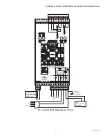
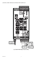
Viewing heads are wired to the appropriate terminals located
on bottom of the 700ACSP, 700DCSP, P531 or P532 signal
processors. The terminals are listed functionally in Table 2.
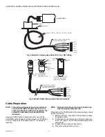
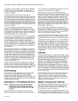
Connectors and cables are shown in Fig. 3, Fig. 4, and Fig. 5.
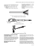
Fig. 3 shows the viewing head cable with the 1/2 in. NPT pipe
fitting and pigtail for use in a conduit. The PF model comes
with 10 feet of Honeywell C330S cable. This cable is
recommended for all new installations. It has ITC and CIC
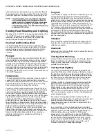
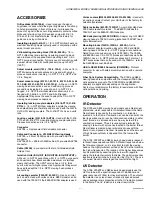
ratings for hazardous location. Figs. 4 and 5 describe the
C330S cable used with the right angle field-wireable
connector. Refer to “Accessories” on page 11 for part
numbers.
S70x/S80x Viewing Head Hazardous
Location Installation of Cables and
Connectors
WARNING
EXPLOSION HAZARD
DO NOT CONNECT OR DISCONNECT THIS
EQUIPMENT UNLESS POWER HAS BEEN
REMOVED OR THE AREA IS KNOWN TO BE
NONHAZARDOUS.
SUBSTITUTION OF COMPONENTS MAY IMPAIR
SUITABILITY FOR CLASS I, DIVISION 2.
AVERTISSEMENT
RISQUE D'EXPLOSION
NE PAS DEBRANCHER TANT QUE LE CIRCUIT EST
SOUS TENSION, A MOINS QU'lL NE S'AGISSE
D'UN EMPLACEMENT NON DANGEREUX.
LA SUBSTITUTION DE COMPOSANTS PEUT
RENDRE CE MATÉRIEL INACCEPTABLE POUR LES
EMPLACEMENTS DE CLASSE I, DIVISION 2.
The S70x/S80x viewing heads must be installed with a
connector and cable assembly that maintains the ingress
protection at the S70x/S80x viewing head. Additionally, ITC/
CIC approved cable installed in cable tray, or ITC/CIC
approved cable in metal conduit must be used between the
S70x/S80x and Signal Processor. Pre-assembled connector/
cable assemblies are listed below that provide the proper seal
at the viewing head, and meet ITC/CIC approvals. A field wire-
able connector that provides a proper seal at the viewing
head, along with ITC/CIC rated raw cable are also available
and listed below. The cable installation must conform to the
latest version of the National Electric Code, or Canadian
Electrical Code for Class I, Division 2 hazardous locations.
Additionally, the connector must be secured as follows: hand-
tighten the connector at viewing head, until it can no longer be
turned. Continue tightening the connector an additional 180
degrees using pliers, or similar tool.
WARNING
Over-tightening the connector can damage the
connector or housing.
Damage will void warranty and hazardous location
approvals. Do not exceed 180 degrees of further
rotation after hand tightening!
Verify that connector cannot be loosened by hand. This is
required for hazardous location installations.
ASY785 – Pre-assembled connector with led indicators and
50 foot cable assembly, IP67 rated with CIC/ITC approved
cable.
ASY785-200 – Pre-assembled connector with led indicators
and 200 foot cable assembly, IP67 rated with CIC/ITC
approved cable.
C330S – ITC/CIC rated 4 conductor 22g cable with drain wire,
and overall shield.
ASY786 – Field wireable connector with led indicators , IP67
rated.
Table 2. Terminal Descriptions.
700ACSP or
700DCSP
Terminal
P531 or
P532
Terminal
Description
VH SIG
VH3 SIG
Flame Signal from Viewing Head
VH SC
VH3 SC
Shutter Drive Signal to Viewing
Head
VH +V
VH3 +V
+24VDC Power to Viewing Head
VH GND
VH3 GND
GND Signal Ground

