XLS140 Installation Manual Form Number 95-7673-3 P/N 51927:C 12/06/2005
63
Fire/Security Applications
Applications
4.4.4 Programming
The control panel can communicate with any number of security devices. To do so, program the
points as follows:
1. Select the address of the module(s) to be used for security.
2. Select the Type Code
SECURITY
.
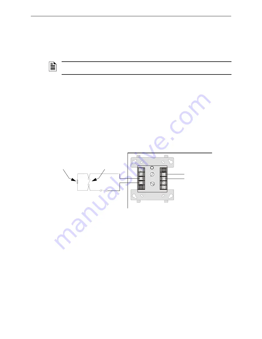
4.4.5 Wiring for Proprietary Security Alarm Applications
Table 4.4 shows typical wiring for proprietary security alarm applications with XLS-MM-A/
TC809A1059 modules. Note the following:
•
The module is programmed with software
SECURITY
Type Code.
•
Supplementary use only applies to UL-listed systems.
•
NAC devices used for security cannot be shared with fire NAC devices.
•
Refer to the
Device Compatibility Document
for compatible NAC devices.
•
All monitor modules used for security application must be installed in the XLS140 cabinet
with STS-1 Security Tamper Switch.
Figure 4.4 Wiring Diagram for Proprietary Security Alarm Applications
NOTE:
For detailed instruction on programming Type Codes, refer to the
XLS140 Programming
Manual.
8
9
8
8
9
9
10
11
12
13
14
15
0
0
1
1
2
2
3
3
4
4
5
5
6
6
7
7
0
1
2
3
4
7
6
5
TENS
ONES
ADDRESS
LOOP
–
+
XLS-MM-A
(Note: TC809A1059 has same connections)
UL-listed, normally-closed
security switch
UL-listed,
normally-open
security switch
SLC
Channel
A or B
XLS140 Protected Premises Unit
n
fs
6
40
-b
ur
g.
cd
r
UL-listed 47K
End-of-Line Resistor
(provided with module)
Summary of Contents for XLS140
Page 8: ...8 XLS140 Installation Manual Form Number 95 7673 3 P N 51927 C 12 06 2005 ...
Page 57: ...XLS140 Installation Manual Form Number 95 7673 3 P N 51927 C 12 06 2005 57 Notes ...
Page 68: ...68 XLS140 Installation Manual Form Number 95 7673 3 P N 51927 C 12 06 2005 Notes ...
Page 87: ...XLS140 Installation Manual Form Number 95 7673 3 P N 51927 C 12 06 2005 87 ...


