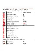
Function switch
S1
/
S2
(
S1
and
S2
are located on the back of
the controller insert. To move the functi-
on switch insert, remove it as described
in the installation instructions.)
n
Function switch S1
"Heating – Cooling"
In air-conditioning systems, the control-
ler can be used also to regulate the cooling load. The feedback of
the setting value (valve position) to the controller is provided by
means of a potentiometer in the servomotor, instead of the flow
sensor.
S1
è
H
(Heating) = factory basic setting
S1
è
K
(Cooling)
In setting
K
the following mean:
LED display
red
– colder
(greater cooling load)
LED display green
– hotter
(less cooling load)
n
Function switch
S2 "Target Value Definition"
S2
è
2
(target value in the pro. range, like setting knob
B
)
= factory basic setting
S2
è
1
(Operating point is always at the target value)
Position
1
of the switch is appropriate for example for mixing
chamber or greenhouse regulations. With this setting the entire
operating characteristic curve goes only in one direction.
Position the setting knob
B
always on
50
.
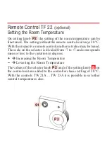
S1
S2


