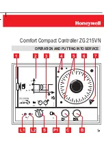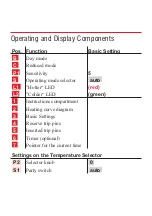
Operating and Display Components
Pos. Function
Basic Setting
B
Day mode
C
Reduced mode
P1
Sensitivity
5
S
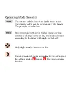
Operating mode selector
auto
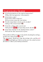
L1
”Hotter“ LED
(red)
L2
”Colder“ LED
(green)
1
Instructions compartment
2
Heating curve diagram
3
Basic Settings
4
Reserve trip pins
5
Inserted trip pins
6
Timer (optional)
7
Pointer for the current time
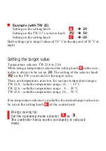
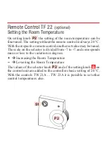
Settings on the Temperature Selector
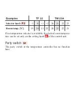
P2
Selector knob
0
S1
Party switch
auto

