background image

4

Honsel  

VVG

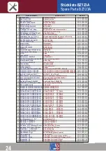
Stückliste BZ103A

Spare Parts BZ103A

22

POS

BESCHREIBUNG

DESCRIPTION

NR / NO.

1

Hydraulikgehäuse 

hydraulic housing  

321.102.000.001

2

Hydraulikkolben 

hydraulic piston

321.102.000.002

3

Pneumatikkolben  komplett

pneumatic piston

321.102.000.003

4

Deckel für Luftanschluß

cap for air supply

321.102.000.004

5

Vordere Hülse lang 

front sleeve

321.101.000.016

6

Stiftsicherung komplett

safty device

321.102.000.006

7

Auslöseventil 

release valve

321.102.000.007

8

3/2 Wegevent. m.IV-Absg. 

3/2-port valve with interval suction

321.103.000.008

9

Filterklemme mit O-Ring

locking screw with o-ring

321.102.000.009

10

Blindstopper m.O-Ring f.Ventil

plug with o-ring

321.101.000.049

11

Ventilverlängerung R1/4

valve extension R1/4

321.121.000.052

12

Ölablaßschr. kpl. m. O-Ring

cheese head bolt M 4 x 6 compl. with o-ring

321.101.000.027

13

Zylinderboden mit Mutter 

bottom of pneumatic cylinder

321.101.000.008

14

Ventilabdeckung komplett

valve housing

321.103.000.014

15

Schlauchabdeckung 

hose covering

321.102.000.015

16

Stopper links 

left stopper

321.103.000.016

17

Stopper rechts 

right stopper

321.103.000.017

18

Stopper Rückseite 

back stopper

321.103.000.018

19

Drücker komplett

trigger complete

321.102.000.016

20

Verschlußkappe Stiftsichrung

closing lid

321.102.000.017

21

Stoßdämpfer PNK-Kolben 

buffer for piston

361.013.300.023

22

Logo

Logo

321.000.003.002

23

Typenschild klein 

Type sign

321.000.003.021

24

Zylrohr vern. 75x107   

cylinder tube

321.102.000.020

25

Schlauchverbindungsstutzen PK3

hose connecting nozzle

321.801.000.027

26

Nickel-Abschl.-Ring 

nickel ring

321.101.300.002

27

Kontermutter M 12x1   

lock nut M 12x1

321.102.000.023

28

Vacuumdüse 

vacuum nozzle

321.121.000.121

29

Zwischenstück

piston extension

321.102.000.025

30

Aufhängebügel 

hanger

321.080.000.011

31

Senkschr.M 6x16 DIN7991 * Isk

countersunk bolt DIN 7991 - M6 x 16

321.102.000.027

32

Linsenschr.Krschl.  M 4 x 25

cross slotted oval head screw DIN 7985 - M4 x 25

321.101.000.025

33

Zyl.Stift  3,0x20  m6 DIN 7  "

pin DIN 7 - 3,0 x 20  m6

321.080.000.034

34

Zahnscheibe   4,3 mm verzinkt

tooth lock washer  DIN 6797 - 4.3 A

321.101.000.028

35

Passscheibe DIN 988-14x20x1

adjusting washer DIN 988-14x20x1

321.102.000.033

36

Seegerring IV 20  f. Bohrungen

lock washer IV - 20

321.121.000.033

37

Zugfeder-Strang 0,25x5x25

bend protection  0,25x5x25

321.701.000.050

38

Druckfeder 0,32x3,2x9,4  102AV

pressure spring 0,32x3,2x9,4

321.102.000.036

39

Führungsband ø30

guide ring 

321.101.000.034

40

Hydraulikdichtung TU 13

hydraulic sealing TU 13

321.102.000.038

41

Hydraulikdichtung TU 30

hydraulic sealing TU 30

321.100.000.017

42

O-Ring 70.0x4.0   NBR 70°Shore

o-ring  70.0x4.0        70° Shore

321.101.000.038

43

O-Ring 69.0x3.0   NBR 70°Shore

o-ring  69.0x3.0        70° Shore

321.101.000.039

44

O-Ring 33.0x1.5   NBR 70°Shore

o-ring  33.0x1.5        70° Shore

321.200.100.046

45

O-Ring 31,5x1.5   NBR 70°Shore

o-ring  31,5x1.5        70° Shore

321.102.000.043

46

O-Ring 26.0x2.0   NBR 70°Shore

o-ring  26.0x2.0        70° Shore

321.102.000.044

47

O-Ring 18.0x1.0   NBR 70°Shore

o-ring  18.0x1.0        70° Shore

321.010.000.010

48

O-Ring 15.0x2.0   NBR 90°Shore

o-ring  15.0x2.0        90° Shore

321.101.000.042

49

O-Ring 13.0x1.5   NBR 90°Shore

o-ring  13.0x1.5        70° Shore

321.102.000.047

50

O-Ring 10.0x1.0   NBR 70°Shore

o-ring  10.0x1.0        70° Shore

321.102.000.048

51

O-Ring 9.0 x1.5   NBR 70°Shore

o-ring   9.0x1.5        70° Shore

321.200.100.040

52

O-Ring 8.0 x1.0   NBR 70°Shore

o-ring   8.0x1.0        70° Shore

321.102.000.050

53

O-Ring 7.0 x1.5   NBR 70°Shore

o-ring   7.0x1.5        70° Shore

321.101.000.044

54

O-Ring 7.0 x1.0   NBR 70°Shore

o-ring   7.0x1.0        70° Shore

321.101.100.015

55

O-Ring 6.0 x1.0   NBR 70°Shore

o-ring   6.0x1.0        70° Shore

321.101.000.045

56

O-Ring 3.0 x1.35  NBR 90°Shore

o-ring   3.0 x 1.35     90° Shore

321.101.000.047

57

O-Ring 3.0 x1.35  NBR 70°Shore

o-ring   3.0 x 1.35     70° Shore

321.102.000.055

58

Hut-Manschette       H   7-6

cup leather H 7-6

321.100.000.026

59

Abstreifer Ý 13x18x3,5

scraper Ý 13x18x3,5

321.102.000.057

60

Siebfilter  8x12 mm  (98ve011)

filter  8x12 mm

321.102.000.059

61

Schlauch  PU-3 schwarz 170 mm

hose PU3, black 170 mm

321.102.000.060

62

Schlauch  PU-3 blau    170 mm

hose PU3, blue 170 mm

321.802.000.049

63

Druckfeder     1,25x9,5x42

pressure spring

311.045.000.013

64

Spannhülse

clamping sleeve

311.045.000.010

65

Spannbacken (3 tg)

set of clamping jaws ( 3 parts )

321.070.000.241

66

Führungshülse

guide sleeve

311.055.000.020

67

Mundstück 4.8/5.0

nose piece for rivet-ø 4,8 + 5,0mm ( 3/16" )

321.085.000.125

68

Mundstück  4.0   

nose piece for rivet-ø 4,0mm ( 5/32" )

321.085.000.124

69

Mundstück  3,0/3,2

nose piece for rivet-ø 3,0 + 3,2mm ( 1/8" )

321.085.000.123

70

Mundstück  2.4

nose piece for rivet-ø 2,4mm ( 3/32" )

321.070.000.240

71

Stiftauffangbehälter  gebohrt

mandrel container

321.082.000.010

Summary of Contents for VVG BZ103A

Page 1: ...nstruction manual Notice d instruction Guia de instrucciones Istruzioni per I uso Gebruiksaanwijzing Bruksanvisning Bruksanvisning Betjeningsvejledning Käyttöohje Instrukcja obslugi Kullanim El Ktabi GB F E I NL S N DK SF PL TR MADE IN GERMANY ...

Page 2: ...ung vor der ersten Inbetriebnahme genau zu lesen Sie vermeiden so unnötige Fehler bei der Bedienung und erhalten wertvolle Hinweise zur richtigen und notwendigen Pflege i Thank you for buying this first class BZ tool for blind rivets produced by the companies of the HONSEL Group HONSEL designs and produces rivet technology for decades The experience and the permanent and continuous development tur...

Page 3: ... 25 26 27 28 29 30 31 4 5 6 8 9 12 13 14 15 19 20 21 22 23 Teileliste Geräte zeichnung BZ123A Konformitätserkläruing Geräuschinformation Produktinformationen Niet Technik Online Hilfen Adressen The tool General information Preparations Safety instructions Processing action Maintenance and care Overview Spare parts and drawing BZ103A 24 25 26 27 28 29 30 31 4 5 6 8 9 12 13 14 15 19 20 21 22 23 Spar...

Page 4: ...AUF DEN SEITEN 20 21 DETAILS ON PAGES 20 21 MUNDSTÜCKE NOSEPIECES X L W H G V UNTERER DRUCKLUFTANSCHLUSS LOWER COMPRESSED AIR CONNECTION JUSTIERUNG DER INTERVALLABSAUGUNG ADJUSTMENT OF CLEARANCE EXHAUSTION AKTIVIERUNG DEAKTIVIERUNG DER INTERVALLABSAUGUNG ACTIVATION DEACTIVATION OF CLEARANCE EXHAUSTION 4 ...

Page 5: ...len lassen Diese Angaben finden Sie zur Kontrolle ggf auch auf dem Zylinderaufkleber auf dem Gerät Jeder Anwender muss im Umgang mit dem Werkzeug geschult sein Allgemeine Hinweise General Information Store the tool in original packaging generally Store the tool dust free and dry in any case After a longer period of non use we advise to change the hydraulic oil page 17 You need the following tools ...

Page 6: ...Å OLIESTAND ÖLJYN MÄÄRÄ POZIOM OLEJU YAG SEVIYESI OIL LEVER BETRIEBSDRUCK PRESSION D UTILISATION PRESSION DE UTILIZACION PRESSIONE DI UTILIZZO LUCHTDRUK ARBETSTRYCK ARBEIDSTRYKK ARBEJDSTRYK KÄYTTÖPAINE CISNIENIE SPREZONEGO POWIETRZA CALISMA BASINCI OPERATING PRESSURE ZUSTAND DER SPANNBACKEN CONDITION OF THE JAWS ETAT DES MORS ESTADO DE LAS MORZADAS STATO DELLE PINZE STAAT VAN DE TREKKLAUWTJES SPÄN...

Page 7: ...ONE POWIETRZE KURU HAVA DRY AIR ÖL HUILE ACIETE OLIO OLIE OLJA OLJE OLIE ÖLJYÄ OLEJ YAG OIL WASSER EAU ACQUA AQUA WATER VANN VANN VAND VESI WODA SU WATER i SF PL TR Honsel VVG WEITERES DRUCKLUFTZUBEHÖR AUF ANFRAGE ÜBER DEN FACHHANDEL VERFÜGBAR ADDITIONAL ACCESSORIES FOR COMPRESSED AIR HANDLING AVAILABLE ON REQUEST FROM YOUR LOCAL DEALER GB D 7 ...

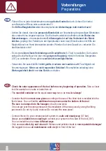
Page 8: ...e Luft Feuchtigkeit und Verunreinigungen führen zu nicht reparablen Schäden Wir empfehlen unbedingt eine Wartungseinheit direkt vor das Gerät zu schalten GB Preparations Check the outer appearance of the tool before every beginning of operation Take a closer look for example on cracks or leaks from oil The mandrell container or the equal cover cap has to be installed always Consider that the corre...

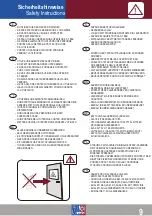
Page 9: ...YCK ÄN 7 BAR RIKTAALDRIG VERKTYGET MOT ANDRA PERSONER ANVÄND SKYDDSGLASÖGON ANVÄND HÖRSELSKYDD KONTROLLER TRYKKLUFTSLANGEN OG KOPLINGEN FØR BRUK ARBEIDSTRYKKET MÅ IKKE OVERSTIGE 7 BAR KOBLE FRA TRYKKLUFTSLANGEN FØR DU UTFØRER NOE ARBEIDE PÅ SELVE VERKTØYET VED PROBLEMER KONTAKT SELGER SIKT ALDRI MED VERKTØYET PÅ ANDRE MENNESKER BRUK VERNEBRILLER OG VED BEHOV HØRSELVERN BRUK VERKTØYET KUN FOR DET R...

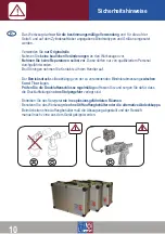
Page 10: ... zu Ihrem Händler auf Der Betriebsdruck sollte abhängig von der zu verarbeitenden Blindnietabmessung zwischen 5 und 7 bar liegen Prüfen Sie die Druckluftanschlüsse regelmäßig auf festen Sitz und sorgen Sie dafür dass die Druckluftleitungen ohne Stolpergefahr verlegt sind Betreiben Sie das Setzgerät nie in explosionsgefährdeten Räumen Benutzen Sie das Werkzeug nie ohne Stiftauffangbehälter oder die...

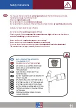
Page 11: ...k of stumbling by bad installed tubes Never use the tool in explosive rooms or surroundings Never use the tool without mandrel container or cover cap If you use the tool without mandrel container the exhaustion has to be deactivated The mandrel must be tipped manually forward out of the tool CHUTE DU CLOU APRÈS RIVETAGE CAIDA DEL CLAVO DESPUÉS DEL REMANCHADO CADUTA DEL CHIODO DOPO LA RIVETTATURA N...

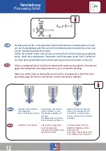
Page 12: ...t you choose the correct rivet for you application which fits to the parameter page 5 of the tool and that the correct nose piece is installed A B C min A B C min i D GB Honsel VVG Einstecken des Nietdornes in das Setzgerät Niet in die Bohrung einführen Beim Auslösen des Gerätes wird der Nietdorn von den Spannbacken gegriffen und gezogen Der Nietdornkopf formt dabei das Schaftende der Hülse um Nie...

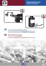
Page 13: ...t als Schlagwerkzeug genutzt werden Tragen Sie bei der Benutzung eine Schutzbrille und Gehörschutz Never point the tool to a person Never use the tool for hammering Always wear savety glasses and ear protection while using the tool Sicherheitshinweise Safety Instructions GB D Honsel VVG 13 ...

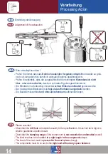
Page 14: ...k angedrückt werden Die Bauteile müssen fest und ohne Zwischenraum aufeinander liegen Honsel VVG Einstellung der Absaugung 5 sec D GB Adjustment of the exhaustion 5 sec All Bitte unbedingt beachten D GB Please consider Check that the drill hole corresponds exactly to the specifications It must not be to big or to small to guarantee a perfect result Check that the clamping range of the chosen rivet...

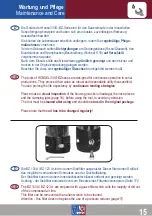
Page 15: ...vorhandenen Schmutzes aus der Druckluftleitung Der Siebfilter kann mit einem Innensechskantschlüssel entfernt und gereinigt werden Achtung der Siebfilter entbindet nicht vom Einsatz eines Filterdruckminderers Seite 17 All D GB The tools of HONSEL VVG BZ series are designed for continuous operation in serial productions They prooved their value as robust and dependable utility thousandfold You can ...

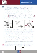
Page 16: ...n den Messingadapter Drücken Sie mäßig Hydrauliköl aus der Spritze in das Setzgerät Warten Sie einige Minuten und wiederholen sie den Vorgang Steigen keine Luftblasen mehr in der Spritze auf Spritze mehrmals leicht hochziehen und eindrücken können Spritze und Messingadapter wieder entfernt werden 6 Schrauben sie die Schlitzschraube wieder ein und beachten Sie dass dabei der zuge hörende O Ring vor...

Page 17: ...e position of the removed screw Plug the filled syringe into ths adapter and press the oil into the tool Repeat the operation after a few minutes If no air blowings ascent while pulling and pushing the syringe a little bit the syringe and the adapter can be removed 6 Reinstall the screw with the o ring Make sure that tis o ring is undamaged Detect the stroke as follows picture 1 Remove the front s...

Page 18: ...les Ergebnis beim Nieten erzielt werden Bitte beachten sie dass die Spannbacken NUR AUF DER RÜCKSEITE gefettet werden dürfen Die Montage erfolgt in umgekehrter Reihenfolge Die Spannbacken gleichmäßig in die Spannhülse gleiten lassen Spannhülse mit Spannbacken wieder auf die Kolbenverlängerung schrauben Die Spannbacken müssen durch Fingerdruck leicht beweglich sein Spannhülse festziehen und vordere...

Page 19: ...xtension The clamping jaws are now approachable and can dumped out for cleaning replacing The teeth of the clamping jaws must be free from damage or abrasion to guarantee an ideal performance Please note the clamping jaws may only be lubricated ON THE BACKSIDE The assembly occurs in the inverted order Slide the clamping jaws smoothly into the clamping sleeve The clamping sleeve with the jaws will ...

Page 20: ... G 90 mm 2 4 5 0 mm 3 8 mm 1 4 4 5 E 50 C 75 dB A 68 32 dB A 2 5 m s 0 62 m s 110 mm 4 0 6 4 mm 4 6 mm 1 4 4 5 E 50 C 75 dB A 69 31 dB A 2 5 m s 1 1 m s BZ 103A BZ 123A D min D max d max 20 8 0 mm Aluminium und Stahl Niete aluminium and steel rivets ...

Page 21: ... Overview 1 2 3 4 5 6 7 8 9 5 7 bar 11 750 N 7 bar 18 mm 2 4 l 1 86 kg 305 mm 310 mm 6 21 5 mm 84 mm P V X H L W F S 5 7 bar 17 730 N 7 bar 25 mm 3 5 l 2 41 kg 310 mm 350 mm 6 23 0 mm 90 mm kg BZ 103A BZ 123A 21 ...

Page 22: ...washer IV 20 321 121 000 033 37 Zugfeder Strang 0 25x5x25 bend protection 0 25x5x25 321 701 000 050 38 Druckfeder 0 32x3 2x9 4 102AV pressure spring 0 32x3 2x9 4 321 102 000 036 39 Führungsband ø30 guide ring 321 101 000 034 40 Hydraulikdichtung TU 13 hydraulic sealing TU 13 321 102 000 038 41 Hydraulikdichtung TU 30 hydraulic sealing TU 30 321 100 000 017 42 O Ring 70 0x4 0 NBR 70 Shore o ring 70...

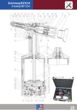
Page 23: ...Honsel VVG Zeichnung BZ103A Drawing BZ103A 23 ...

Page 24: ...25x5x25 bend protection 0 25x5x25 321 701 000 050 39 Druckfeder 0 32x3 2x9 4 102AV pressure spring 0 32x3 2x9 4 321 102 000 036 40 Führungsband ø30 guide ring 321 101 000 034 41 Stangendicht HS250 0130 01 55N hydraulic sealing TU 13 321 102 000 038 42 Stangendicht HS250 0150 01 55N hydraulic sealing TU 15 321 011 000 037 43 Kolbendicht HK155 0300 02 55N hydraulic sealing TU 30 321 100 000 017 44 O...

Page 25: ...Honsel VVG Zeichnung BZ123A Drawing BZ123A 25 ...

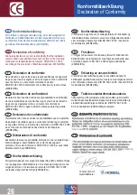
Page 26: ...sono conformi alle seguenti normative o documenti normativi DIN EN 792 1 2008 ai sensi della Direttiva macchine per rivetti a strappo e inserti filettati 2006 42 EG I Konformitätserklärung Declaration of conformity Déclaration de conformité Declaration de conformidad Declaracào de conformidade Dichiarazione di conformità Wij verklaren geheel voor eigen verantwoording dat de klinkmachines voor popn...

Page 27: ... sobre ruído e vibrações NL Informatie over geluid en vibratie DK Støj vibrationsinformation S Ljud vibrationsdata N Støy vibrasjonsinformasjon FIN Melu tärinätieto I valori di misurazione sono stati rilevati in conformità alle norme EN ISO 15744 2008 e EN 28662 1993 La misurazione A del livello di pressione acustica della rivettatrice è in genere inferiore a 80dB A Durante la lavorazione il livel...

Page 28: ...tional individual options to optimize any application Special nose pieces axial tools rivet angle heads or completely process controled automation for serial productions The HONSEL Group offers all possibilities of modern type rivet technology all from one source Neben der BZ Serie für die Verarbeitung von Blindniete stehen mit den Geräten der HONSEL VVG VNG Serie verschiedene pneumatisch hydrauli...

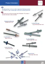
Page 29: ...lind rivets are one of the most used types of fasteners The variety of versions and sizes is nearly unlimited 29 Großkopf Blindniete Large domehead blind rivets Mehrbereichs Blindniete Multigrip blind rivets Dicht Blindniete Sealed blind rivets Hochfeste Blindniete High strength blind rivets Sonderblindniete Special type blind rivets Lackierte Blindniete Painted blind rivets ...

Page 30: ...VIEWER hilft komfortabel bei der schnellen Ermittlung benötigter Ersattzteile D GB The PRODUCT VIEWER helps to locate the required spare parts comfortably and quickly PRODUKT FILME zeigen anschaulich einige Wartungs und Reparaturarbeiten D GB PRODUKT FILME zeigen anschaulich einige Wartungs und Reparaturarbeiten D GB With the help of short films some of the main maintenance actions are shown Regis...

Reviews: