_________________________________________________________________________________________________
______________________________________________________________________________________
U326_UVAintAS102_B_e_210316
7/15
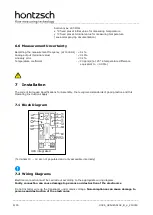
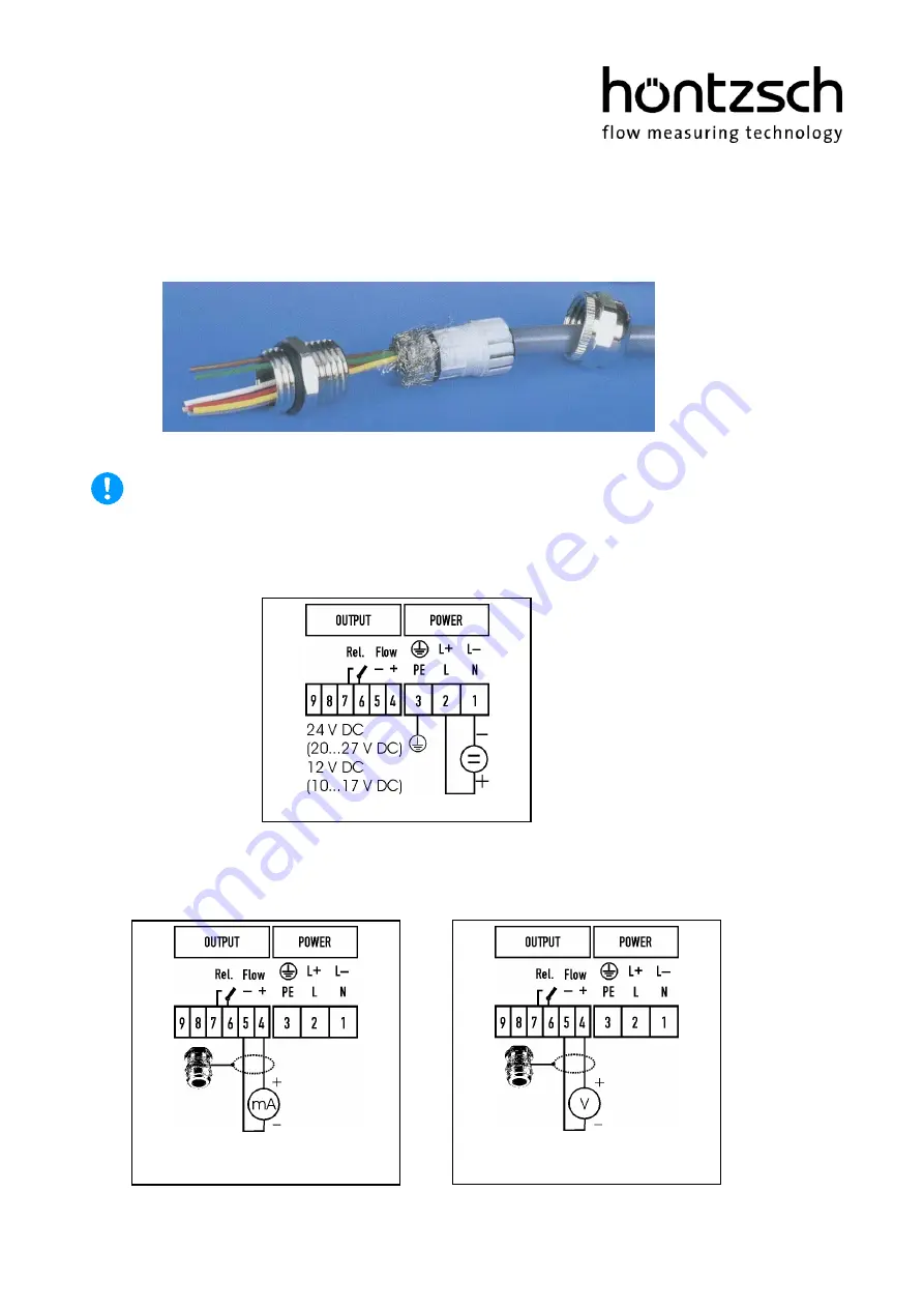
In this connection and depending on the configuration of the equipment, one of the following wiring dia-
grams must be taken into account. Wiring diagrams for measuring systems in customer-specific design will
be supplied separately.
7.2.1
Shielding contact at cable bush
7.2.2
Power supply
Before connecting please check that the power supply is within the specification. Remove the cover of the
integrated UVA to reveal the type plate with the relevant information.
7.2.3
Analog output v
P
= protective earth
4-20 mA
Resistance max. 400 Ohm
0-10 V
Impedance 1 kOhm

