background image

Summary of Contents for Seafurl 705

Page 1: ...WICHT THISUNITIS COMPLETF ilLH 5XW INSTALLAT ION MANUAL AND OWNEFI S MANUAL AUGUST1987 rs h s ab n rf A g ry V7 8 s V c v I t _ ...

Page 2: ...s ary to follow the simpleguidelines listed below 1 Rinse the bearingsregularlywith fresh water 2 Watchfor halyardwrap Look up 3 If it jams find outwhy don t forceit 4 tt I reat tnls unlt like other I reat tnls unlt llKe any otner equipment inspectit regularly 5 If anyproblempersists callyour dealer ...

Page 3: ...Eh ftT GWO 2 ffire Figure l ...

Page 4: ...ocket 1i Hali ard Sg rrei Assemblr 5 FeedSect ion 6 SplicePieces 7 Luff Bearings 8 Luff Secri rns QUANTITY I I 2 halves I I 2 h rlvcsper luif sec I pcr lufi sec plus I cxtr i determinedbr headstaylengrh 2 halves 1 per luff sec i Hack saw 6 Fine metal file or sandpaper 7 Hamrner TOOLS REQUIREDFOR ASSEMBLY i Tape Measure 2 Rigging tape l Felt tip marker 4 Allen wrench rincluded t ...

Page 5: ... GD Figure2 ...

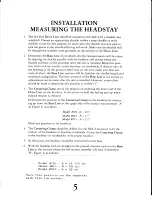
Page 6: ...al as adjustmentscan be made after the unit is installed However everyeffort shouldbe made to determine this posirion to withint 1 The Centering Clamp servesthe purposeof centeringrhe lower end of the Drive Unit on the headstay It alsoservesto hold the furling unit up when halyardtension is released Determine the position of the Centering Clamp on the headstayby measur ing up from the BaseLine to ...

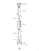
Page 7: ... I r l v n f I Luff Bearings Top Bearings SplicePieces T t An G I 6 r m fi 1 3 ...

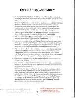
Page 8: ...adstay Slide it down over the Splice Pieces that are now sticking our of the top of the Feed Section Rivet the Luff Section to rhe Splice Pieces Twist anorher Luff Bearing onto the headstayand insert it into the top of the Luff Section Rivet another set of splice piecesinto the top of the section Repeatstep5 until the top of the Luff Section assemblycomeswithin 6 of the top of the headstay The las...

Page 9: ...FeedSection vr r Crlt fi Artrack Socket J tlu Forward rack Socket DriveUnit w Figure3A O s centeringclamP 8 ...

Page 10: ...o assembiethe feed section ro rhe drive unir attach the aft tack socket to the feed section Figure 3 and insert into drive assembly aligning the knob on the tack socketwith the hole in the tube Slide the Forward tacksocket into theothersideandtightenthescrew Usesilicone sealon the threadsto prevenrloosening 9 Slide the Halyard Swivel Assembly down over rhe top of the headstay The tabson the insert...

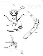
Page 11: ...IT lT i 1 between top sheave 3 10 ...

Page 12: ...ve Sheave The endsof the furling line should be splicedto form a continuous loop Be sureto run the line through the fairlead blocksand the cover window Figure4 before splicing The loop should be long enough to reachback to the cockpitwhereit can be leadto a winch or to a cleat The angle between the headstayand furling line leading to the lst fairlead blocks should be 90 as shown in Figure 6 This w...

Page 13: ...may want to have a rag handy to catch the excess t 7D 40 which may run down To flush the Halyard Swivel Assembly simply spray or pour water into the bear ings while turning the Swivel Cups F igure10 7 An occasionalsquirt of WD 40 in the bearings is also recommended If after extensive use or at any time stickinessor friction becomesexcessivesuch that the bearings are not functioning acceptably remo...

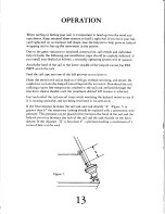
Page 14: ...rooves as you hoist it Hoist the swivel and sail as high as it will go without straining and secure Be careful not to hoist the halyard swivel beyond the extrusion Downhaul rhe sail utilizing a spare line temporarily attachedto the sail tack and lead rhrough the line drive sheaveshackleuntil the maximum desired luff tension is achieved Furl and unfurl the sail severaltimes while watching the halya...

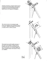
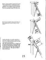
Page 15: ...s toolow decreasing theangle betweentheheadstay sheave andhalyardsheave to 6degrees Whilethisinstallation mayfunction it wouldbebetterto attachapennant Thepennant increased theheightandangleof theswivelto theheadstay Pennants maybe installed onthetackofthesailinsteadofatthe head Thisprovidesbetterleewardvisibilityand reduces possible damage to thesaildueto heavy seaconditions L4 ...

Page 16: ...provedsothereis a betterangleandtheexposed halyardis much shorter Anotheralternativeis to installastrapbaleor blockthatrestrainsthehalyard Withoutsucha device thecondition illustratedin Fig 12would cause halyardwrapproblems Note The angle shown here is exaggerated for illustration purposes The bale should be placed so that halyard just lightly rubs on the inside of the bale We recommend the Foresp...

Page 17: ...tt I I i Figure8 9 705 El0 915 x Et z 9 2 13 Y l4 16 24 T6 ...

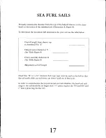
Page 18: ...StemheadPin E Halyard swivel deduction Y SeeTable Figure 8 Drum assemblydeduction X SeeTable Figure 8 Maximum sail luff length Hood Size X or 3 16 diameterbolt rope tape must be usedon the luff so that the sail easilyslidesup and down yet doesn tpull out in heavyair In order to accommodatethe halyard swivel and tack shackles the head and tack rings in the sail should be no larger than 1t pressring...

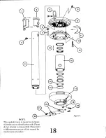
Page 19: ...YL II w t 15 f l NOTE Thisexploded viewis meantfor purposes of product parts identification only Please do not attempt to disassemble Pleaserefer to Maintenance section of this manual for maintenanceprocedure 18 Figure9 I ...

Page 20: ... x 1 4SHCS 6402 00r X ichard tZtZ 6412 00r 64rr 00r l8 24x 3 8 half Dog pt SetScrew 639r 00r 6397 00r 6427 00r Il4 20 x 3 4RHMS 6478 000 6410 001 RSN168S 6401 001 6396 00r I l4 20LIex JamNut Il4 20 x 3 4SHCS 6429 00r rl4 20 x 1RHMS ll4 20Hex JamNut 643r 000 1960 001 5919 001 I 4 20x3 8 SHCS t9t8 001 Wichard l2l3 1983 001 5982 00r 3 8 r6x1 4half Dog pt SetScrew 6021 00 I 5979 001 1984 00 I r 4 20x1...

Page 21: ...g q I qffi NOTE Thisexploded viewis meantfor purposes of product parts identification only Please do not attempt to dsassemble Pleaserefer to Maintenance section of this manual for maintenance procedure Figure10 20 ...

Page 22: ...00r 6430 000 6010 000 SwivelTube HalyardSwivelInserts SpiroloxRing BearingThrust Washer BearingAssembly D Shackle Halyard Swivel Crp ShackleStud Bushing ShackleStud Swivel AssemblyComplete SwivelAssemblyComplete SwivelAssembly Complete 6012 001 6017 001 RSN2OOS 5917 00r 6181 001 Wichard 1213 6011 001 t983 001 5982 00r 6016 001 6018 000 RSN2375 1995 001 6182 001 Vichard l2l4 6015 001 t994 00r 1993 ...

Page 23: ...I g L b FigureI L 22 ...

Page 24: ...r 810 915 705 1 a z 3 4 6 Top Bearing Luff Section Rivet Luff Bearing SplicePiece FeedSection 6428 00r 6432 00r 643r 00r 6404 00r 6433 00r 6019 001 5945 001 t98i 001 6r12 001 6r2t 001 6020 001 5946 001 6007 001 6113 001 6T26 00r 3 16 AluminumDrive Rivet 23 ...

Page 25: ...cified qualityshallbein accordance with HoodYachtSystemsspecifications C The HoodSeaFurl andGeminimustbeinstalledandmaintained properlyandusedundernormalconditionsin the application for whichthey were intended D HoodYachtSystemsshallnotberesponsible for shipping charges or installationlaborassociated with anywarrantyclaims E Terms of this limitedwarrantyshallbe90daysif theproductis usedin commerci...

Page 26: ...ed model tr Gemini SeaFurl n n u StowayMast Stoway Boom lengtlr E LineDriver Other BoughtFrom Installedby Date Didyoureceiveanowner smanual I havereadtheowner smanual andunderstand my system soperation and maintenance requirements Signature E TherearesomethingsI donotunderstand andwouldlikeaHoodRepresentative to contactme HOODYACHTSYSTEMS CORP Maritime Drive Portsmouth RhodeIslandO2BTI 401 683 2e0...

Page 27: ...l 839 HYSUR FAX 10t 683 3009 Note Fax Memo July 18 1997 To John Nantz From Ken Clark Hood Yacht Systems Drive rivits were originally used to hold the top bearings in place A running change was made years ago and we now use a screw with a plastic anchor in each luff groove Editorial comment This is so much better ...

Reviews: