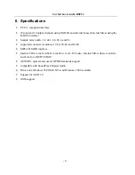
background image

S

OUNDTRACK

 Audio DSP24 

- 10 - 

V. Hardware installation 

Make sure the computer is switched off and unplugged. Remove the external computer cover. 
Check that you have connected the Audio DSP 24 and the XG DB I correctly as described above. 
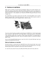
Insert the Audio DSP 24 PCI card into a free PCI slot making sure that it is pressed firmly into 
position and secure it to the computer case. Position the XG DB I along side and secure it to the 
computer case. 

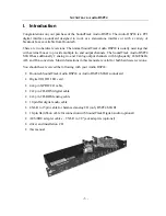
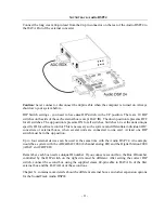
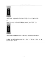
The Audio DSP 24 card system consists of the main PCI card (Audio DSP24) and a secondary 
daughter board (XG DB I). Hook the included gray lead wire to the CNN2 connection socket on 
the Audio DSP24 and then into the daughter card to connect the cards. 


You can use either the analog or digital outputs from the CD ROM drive. The CD digital output 
can be connected to either the CNN3 on the Audio DSP24 or the socket marked J3 on the XG DB 
I. The CD analog output can be connected to CON1 on the Audio DSP24. All required leads are 
included in the packaging. Please check with your CD ROM manufacture to ensure that it supports 
digital output. 

If you own the Audio DSP24 MK II, please connect the 4 XLR to 15pin D-SUB cable to the 15pin 
connector on the backside of the card. 

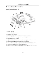
External hardware connection 

External converters are connected to the Audio DSP24 host card by using the thick cream colored 
44-pin cable included with your system. All external converters and optional boxes can be daisy 
chained using the DATA In and DATA Out 44-pin connections (H-BUS). 

To connect the first external box (like the ADC&DAC2000) please follow these directions: 

Summary of Contents for SoundTrack Audio DSP24

Page 1: ...nts improved software and drivers become available Hoontech therefore reserves the right to change specifications without prior notice A S Center Hoontech Co Ltd 4th Flr Minkyung Bldg 332 Songne 1Dong...

Page 2: ...20 VIII Mixer controls 22 Internal Mixer 22 External Mixer 26 IX Hardware settings 29 X Connection with input devices and external boxes 31 XG DB I 31 MK II Analog I O cable 32 SoundTrack Digital Audi...

Page 3: ...2 analog in and 2 anlog output channels with high quality 24bit 96kHz AD and DA converters Most informations in this manual are valid for both hardware revisions You should have received the following...

Page 4: ...n and Mic in preamplifiers with 48V phantom power for condenser microphones DAC III 24bit 96kHz 8 analog balanced outputs AES EBU optical and coaxial S PDIF connections are also provided Digital Modul...

Page 5: ...s or through the digital output of XG DB I The Internal Mixer allows settings for input and output levels for Wave Line In MIC CD In and Auxiliary devices The output signal of the Internal Mixer is al...

Page 6: ...44 1 48 88 2 and 96 supported converter resolution 16 bit 20 bit and 24 bit MPU 401 MIDI interface Internal CD in Line In Mic In Line Out via AC 97 Codec Internal Mixer there is no Mic and Line In on...

Page 7: ...or for optional Digital I O card or analog bracket 6 MIDI connector cable optional 7 Digital Audio connector used when a SoundTrack Digital Audio card is installed 8 CD In can be connected to the anal...

Page 8: ...umper settings for 1 8 Output 4 Bracket connector used when a SoundTrack DAC or Analog Bracket is installed 5 CD In can be connected to the analog output from CD ROM 6 Aux can be connecte to the analo...

Page 9: ...it 96kHz The Mic In Line In Line Out Aux and CD In are routed through the AC 97 Codec on the AudioDSP24 and are controlled by the Internal Mixer S PDIF I O are connected to the XG DB I digital I O boa...

Page 10: ...ou can use either the analog or digital outputs from the CD ROM drive The CD digital output can be connected to either the CNN3 on the Audio DSP24 or the socket marked J3 on the XG DB I The CD analog...

Page 11: ...he system can differentiate individual ADC converters or external boxes when several units are connected to one card At least one DIP switch must be in the up position Up to four external devices can...

Page 12: ...SOUNDTRACK Audio DSP24 12 After everything is connected to the card you can re assemble your PC and continue with the driver and software installation...

Page 13: ...ns drivers for Windows 95 98 ME and NT4 The following instructions pertain to Windows 98 only The installation under Windows 95 or Windows ME is very similar After installation of the Audio DPS24 in a...

Page 14: ...e best driver for your device and click Next Check Specify a location Type in the drivename sound dsp24 driver in the window displayed above and click Next In the alternative you can click Browse and...

Page 15: ...he driver file indicated in the screenshot Click Next At this window complete the installation by clicking Finish Windows will now install the driver for you through a series of installation screens I...

Page 16: ...perties You should see the message This device is working properly Click on the Resources tab you should see the message No conflicts If so congratulations are in order You have successfully installed...

Page 17: ...SOUNDTRACK Audio DSP24 17 You will see the SoundTrack setup logo and see the Windows Setup indicator begin to work as below Next you will see the Welcome to SoundTrack Setup window Click Next...

Page 18: ...lt directory by clicking Next or select your own by clicking Browse then Next Choose the default Program folder name by clicking Next or type in your own and click Next Now you will next see the Sound...

Page 19: ...ompletion window and will be asked if you wish to launch External Links Click Finish if you wish to Finish and launch External Links Declick the Launch the External Links button if you do not wish to...

Page 20: ...ed to the Systray during installation Right clicking the mouse on the icon will open the menu below Clicking on Open External Links will launch External Links With External Links signals can be routed...

Page 21: ...r Clock 4 DAC digital to analog converter represents the outputs Output 1 2 Front output to front speakers when using a digital amplifier or Out 1 2 stereo of the DAC box Output 3 4 Rear output to rea...

Page 22: ...nal Mixer works basically like a normal soundcard and can be used for standard multimedia software or games for example Please see the following section with more details Master Controls the output vo...

Page 23: ...you want to record a signal from the Internal Mixer using the device ADSP24 Int Input n you can control the signal volume and the source in this section With the drop down menu you can select the rec...

Page 24: ...d to control the volume of the Line Input signal on the PCI card itself Please note that the DSP24 MK II does not have this Line In connector You can control the panning and the Line In volume Muting...

Page 25: ...e as well Aux This sections controls the volume of the internal analog Aux input of the PCI card You can control the panning and the Aux volume Muting the channel is possible as well If you are using...

Page 26: ...1 2 and or through the S PDIF Output setup in External Links When you are recording an input signal the External Mixer does not change the signal level This ensures that you are always recording with...

Page 27: ...nnel is possible Also you can control the panning independand for the left and right channel of each stereo device S PDIF Out In the S PDIF Out section you can control the volume of the signal of the...

Page 28: ...SP24 28 Muting the left and right channel is possible independandly Input 1 2 to 7 8 These sections are controlling the volume of the different input channels Muting the left and right channel is poss...

Page 29: ...al Master Clock will control clock timing The Audio DSP24 can be synchronized to an external device or set its own internal rate and impose this rate on the other devices conncted to the digital outpu...

Page 30: ...settings will result in greater latency but fewer playback and recording dropouts Lower buffer settings will result in lesser latency but you may encounter playback and recording dropout problems as t...

Page 31: ...ous connection of several items via the External Links function is possible XG DB I The XG DB I board features CD digital input Optical I O Coaxial I O and AES EBU connectivity with the Audio DSP24 1...

Page 32: ...ection from XG DB I to S PDIF In you must have an active device connected to the coaxial optical or AES EBU input such as a DAT recorder This connection changes the Internal Master Clock option to Ext...

Page 33: ...l 1 2 5 1 8 output for Internal Mixer External Links setup You can make this connection via the option Inputs Add Inputs MK II Input You need to do this in order to us the two input channels This cabl...

Page 34: ...soundcard you can cascade it internally with the Audio DSP24 Connection Align red line on flat cable with triangle marking on the board for proper connection Now the output signal of the SoundTrack Di...

Page 35: ...SP24 card the first card is connected to the card as shown in the picture above The second box is connected to the second data connector of the first box and so on You have to make sure that each box...

Page 36: ...ple please select the corresponding entry in External Links e g Inputs Add Inputs ADC DAC2000 If you use a different external box you can choose General Box Be sure to set the same box ID number in th...

Page 37: ...See section VII in this manual for details ADSP24 Ext n WaveOut 5 6 third stereo wave output device Use this driver to play audio through outputs of an external box See section VII in this manual for...

Page 38: ...al Mixer Additionally the card provides an ASIO 2 0 driver called ADSP24 ASIO It allows access to all 10 input and 10 output channels of the External Mixer in applications that support ASIO like Cubas...

Page 39: ...settings in External Links select the ASIO buffer size we recommend using a value of about 1800 depending on the system performance make sure the option Rate Locked is disabled set the option MultiTra...

Page 40: ...MME ADSP24 10ch 16bit record and playback on all channels with 16 bit resolution MME ADSP24 Digital 24bit to use just the digital in and outputs with 24 bit resolution MME ADSP24 Digital 16bit to use...

Page 41: ...rams like Nuendo Cubasis VST or Cubase VST 5 0 have a very similar setup when using the ASIO driver To setup the Audio DSP24 in Cubase VST please follow these steps call File Hardware settings in Exte...

Page 42: ...and adding VST plugin effects at the same time select Tape Type instead In the upper right corner under ASIO Device select ADSP24 ASIO By clicking on ASIO Control Panel you can also change the sample...

Page 43: ...the channels in the VST Channel Mixer then via Audio Monitors For the outputs you need to open Audio Master In this window you can deactivate a stereo bus for each stereo output These busses can be u...

Page 44: ...Emagic also uses ASIO drivers Follow these steps to setup the application for the Audio DSP24 call File Hardware settings in External Links select the ASIO buffer size we recommend using a value of 8...

Page 45: ...h 24 bit resolution check the box 20 24 Bit Recording exit Logic Audio and launch it again to activate the changes You can get the latest informations about Logic Audio Platinum at http www emagic de...

Page 46: ...MME drivers of the SoundTrack Audio DSP24 launch Cakewalk and select Options Audio The DirectShow Audio dialog will be displayed Click on Drivers You will see a list of MME devices for Input and Outp...

Page 47: ...ts Mixing Latency Basically you can set Buffers in Playback Queue as 4 Settings less than 4 will result in lower latency but the system performance could be lower resulting in possible drop outs Start...

Page 48: ...DSP 24 Call File Hardware settings in External Links Select the ASIO buffer size we recommend to use the value 1800 or lower depending on the system performance Launch BPM Studio and open the Audio I...

Page 49: ...ws you to use the separate outputs of the card with GigaSampler Launch GigaSampler and select Config Outputs Under Wave Out Driver select Audio DSP24 MultiChannel Driver Select the Output channels you...

Reviews: