background image

1   Safety information

WARNING

WARNING:

 Explosion hazard. Do not use the 594810 in the presence of 

flammable anesthetics mixture with air, oxygen, or nitrous oxide.

WARNING: 

Chemicals from a broken LCD display panel are toxic when

 ingested. Use caution when the 594810 has a broken display panel.

WARNING: 

Pulse oximetry measurements and pulse signals can be 

affected by certain environmental conditions, SPO2 sensor application
errors, and certain patient conditions. See the appropriate sections of 
this manual for specific safety information.

WARNING: 

The use of accessories, sensors, and cables other than 

those specified may result in increased emission and/or create invalid 
readings of the 594810.

WARNING: 

Failure to cover the sensor site with opaque material in 

high ambient light conditions may result in inaccurate measurements.

WARNING: 

Do not silence the audible alarm function or decrease the 

audible alarm volume if patient safety could be compromised.

WARNING: 

 The 594810 is a prescription device to be operated only by 

trained personnel.

WARNING: 

 Dispose of batteries in accordance with local ordinances 

and regulations

WARNING: 

 To ensure patient safety, do not place the 594810 in any 

position that might cause it to fall on the patient.

WARNING: 

As with all medical equipment, carefully route patient cables 

to reduce the possibility of patient entanglement or strangulation.

WARNING: 

 Ensure that the speaker is clear of any obstruction and 

that the speaker holes are not covered. Failure to do so could result 
in an inaudiblealarm tone.

WARNING: 

Disconnect the 594810 and SPO2 sensor from the patient 

throughout magnetic resonance imaging (MRI) scanning. Induced 
current could potentially cause burns.

WARNING: 

 To ensure accurate performance and prevent device 

failure, do not subject the 594810 to extreme moisture, such as direct 
exposure to rain. Such exposure may cause inaccurate performance or 
device failure.

WARNING:

Do not use either the 594810, SPO2 sensor, or cables that 

appear damaged. 

WARNING:

Do not lift the 594810 by the sensor or extension cable 

because the cable could disconnect from the 594810 and the 594810 
may drop on the
patient. 

 -6-

Summary of Contents for 594810

Page 1: ...594810 Hopkins Handheld Pulse Oximeter Instructions for Use Hopkins Medical Products ...

Page 2: ...thbelt Drive This manual has a revision number This revision number changes whenever the manual is updated due to software or technical specification change Contents of this manual are subject to change without prior alarm Revision number 1 0 Revision Date 7 2018 REVISION HISTORY PRODUCT INFORMATION Caledonia MI 49316 USA ...

Page 3: ... so that it can be obtained conveniently when needed INTENDED AUDIENCE This manual is geared for clinical professionals who are expected to have a working knowledge of medical procedures practices and terminology as required for monitoring of critically ill patients ILLUSTRATIONS All illustrations in this manual serve as examples only They may not necessarily reflect the setup or data displayed on ...

Page 4: ...lume 5 3 2 Select Patient Type 5 3 3 Set alarm Limit 5 3 3 1 PR High Low alarm Limit 5 3 3 2 Set SPO2 Low alarm Limit 5 3 4 When an Alarm Occurs 5 3 5 RESET TO DEFAULT 5 4 SpO2 PR measurement 5 4 1 Place sensor on the finger of patient 5 4 2 Display description 5 5 Alarms 5 5 1 Alarm Categories 5 5 2 Alarm Levels 5 5 3 Alarm Indicators Physiological Alarm Messages Technical Alarm Messages Contents ...

Page 5: ...6 27 23 24 20 7 1 Cleaning 7 Maintenance 7 3 Disposal 9 Specifications 10 EMC information 7 2 Safety Checks 8 Accessories 6 Summary of Spo2 pulse rate accuracy testing 5 6 Measurement Limitations 11 Warranty 30 20 ...

Page 6: ... is a prescription device to be operated only by trained personnel WARNING Dispose of batteries in accordance with local ordinances and regulations WARNING To ensure patient safety do not place the 594810 in any position that might cause it to fall on the patient WARNING As with all medical equipment carefully route patient cables to reduce the possibility of patient entanglement or strangulation ...

Page 7: ...he configuration in which it is to be used The medical electrical equipment needs to be installed and put into service according to EMC Information The use of patient cable and other accessories not supplied by the manufacturer may result in increased emissions or decreased immunity of the equipment The equipment should not be used adjacent to or stacked with other equipment refer to the recommende...

Page 8: ...lass II equipment Type BF applied part defibrillation protected European community representative The following definition of the WEEE label applies to EU member states only This symbol indicates that this product should not be treated as household waste Resistant to liquid ingress Power supply connector Caution warning Federal U S Law restricts this device to sale by or on the order of a physician ...

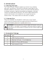
Page 9: ...uration measurement This measurement is referred to as SpO2 3 2 Intended Use The pulse oximeter is indicated for continuous or spot check monitoring of functional arterial oxygen saturation SpO2 and pulse rate of adult patients in hospitals and clinics 3 3 Included in Package Quantity Item 1 594810 pulse oximeter 3 Alkaline AA size 1 5 volt batteries 1 594301 Y Probe SPO2 sensor 1 Instructions for...

Page 10: ... lights yellow without flashing 1 4 7 10 NOTE 2 5 8 Power on off Set Sensor connector 3 6 9 Up Down Alarm silence Cord hole 3 5 Display Screen Elements SPO2 area of display Pulse beats per minute BPM area of display 1 3 Pulse amplitude index signal intensity bar 5 2 4 6 Measured SPO2 Measured BPM Perfusion index signal intensity bar 1 2 3 4 5 6 7 8 9 10 1 2 3 4 5 6 10 ...

Page 11: ...when approximately 15 minutes of operation is available The batteries should be replaced 4 3 Install the Batteries 1 Turn off power Pull the battery cover downward toward the bottom of the 594810 and then remove the battery access door 2 Install three AA size batteries make sure to put the correct orientation 3 Replace the battery cover Caution If the 594810 is to be stored for a period of three m...

Page 12: ...s rain 5 594810 operation 5 1 Introduction The parameters of the 594810 are preset to factory default values See Table 2 Table 2 lists the parameters ranges available and the factory default values The parameters may be set on an individual basis by the clinician and will remain in effect until the 594810 is turned off Table 2 Parameter Ranges Parameter Range selections Factory defaults SpO2 Upper...

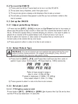
Page 13: ... then goes out 3 The system gives a beep and displays the startup screen 4 The startup screen disappears and the pulse oximeter enters the main screen 5 3 Set up the 594810 5 3 1 Adjust pulse Beep Volume 1 Press button SET VOL and press Up Down button to increase or decrease the pulse beep volume then set the volume between 0 and 10 Note When the pulse beep volume display is shown the user is able...

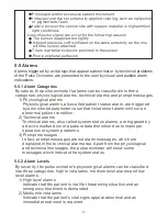
Page 14: ...ps to take proper actions 1 Check the patient s condition 2 Confirm the alarm parameter or alarm category 3 Identify the source of the alarm 4 Take proper action to eliminate the alarm condition Note The pulse rate alarm limit range is 25 to 250 The upper value of the pulse rate low alarm limit is limited one number lower than the pulse rate upper alarm limit The pulse rate low alarm limit cannot b...

Page 15: ...sor or extension cable to the 594810 SpO2 sensor port 5 4 1 Place sensor on the finger of patient 5 4 2 Display description perfusion index signal intensity bar Measured SPO2 1 2 Measured BPM 3 4 Pulse amplitude index signal intensity bar 2 4 5 1 5 3 5 RESET TO DEFAULT 1 Press button SET CON and Press the Up Down button set the value to SET 2 Press button SET 3 Reset to default value 5 Make sure th...

Page 16: ...e patient cabling to avoid entanglement Do not use the SpO2 sensor on a limb with an intravenous infusion or arterial catheter in place Do not use the SpO2 sensor on a limb where the NIBP cuff is applied This may result in inaccurate SpO2 reading due to blocked blood flow during cuff inflation WARNING Pulse oximetry readings and pulse signals can be affected by certain ambient environmental conditio...

Page 17: ...Physiological alarms also called patient status alarm are triggered by a monitored parameter value that violates set alarm limits or an abnormal patient condition 2 Technical alarms Technical alarms also called system status alarms are triggered by a device malfunction or a patient data distortion due to improper operation or system problems 3 Prompt messages In fact prompt messages are not alarm ...

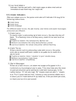
Page 18: ... High level alarms triple double triple double beep Medium level alarms triple beep Low level alarms single beep 3 Alarm Messages When an alarm occurs an alarm message will appear in the technical or physiological alarm area This time lists only the most important physiological and technical alarm messages In the tables below H means high M means medium and L means low The Cause and actions column...

Page 19: ...s weak and please pay attention to sensor location and patient status L Alarm SpO2 Too High SpO2 Too Low PR Too High PR Too Low No Pulse Low Perfusion Low signal Quality Alarm lamp is yellow and flashing The screen will show Low Signal Quality M The pulse signal was too weak Check the patient s condition condition SpO2 sensor and measurement site Technical Alarm Messages Alarm Alarm Message Cause a...

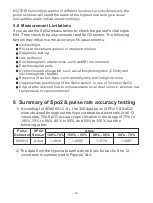
Page 20: ...ccuracy specification in the range of 70 to 100 70 to 80 80 to 90 and 90 to 100 is as the following table Pulse Oximeter SPO2 Sensor Arms 100 70 100 90 90 80 80 70 2 The data from the hypoxia breathe down trials for each of the 12 volunteers is summarized in Figures 1 2 594810 Adult 1 3910 1 2555 1 3774 1 5687 Ambient light Physical movement person or imposed motion Diagnostic testing Low perfusion...

Page 21: ...Figure 1 Bland Altman 21 ...

Page 22: ...Figure 2 Linear Regression 22 ...

Page 23: ...nfect the monitor 1 Saturate a soft cloth or wipe of hospital grade disinfectant PDI Cavicide Sanizide etc 2 Lightly wipe each exterior surface using the saturated soft cloth Adhere to disinfectant manufacturer guidelines for efficacy and dry time Caution Before attempting to clean a SpO2 sensor read the directions for use enclosed with the sensor Each sensor model has specific cleaning instructions...

Page 24: ...her accessories may cause damage to the pulse oximeter Disposable accessories are designed for single person use only Reuse of them may cause a risk of contamination and affect the measurement accuracy Check the accessories and their packages for any sign of damage Do not use them if any damage is detected Inspect the application site every 2 hours and relocate the sensor for ringer finger again mo...

Page 25: ...e sensor site every 2 hours for skin integrity and relocate the sensor every 2 hours according to steps 1 2 Reusable Neonatal Wrap SpO2 Sensor Foot hand or finger Child or Neonatal Infant Weight range 594301 Neonatal Y Probe Wrap Sensor Usage 1 Attach the sensor to a well perfused fleshy portion of the infant s hand or foot 2 Place the sensor to the patient with the light source LED on the top of th...

Page 26: ...r Power supply connecto Color LCD 2 4 1 Gives audible alarm 45 to 85dB and button tone Supports Pitch Tone and multi level volume 1 lighting green and yellow 1 lighting red and yellow 1 9 pin type D connector 1 used to connecting the Charger stand Communication port Data storage Shelf life Alkaline batteries Quantity Specification Specification Run time Shutdown delay No No 5 Years 3 1 5 V AA 2000 m...

Page 27: ...ance The 594810 uses RF energy only for its internal function Therefore its RF emissions are very low and are not likely to cause any interference in nearby electronic equipment The 594810 is suitable for use in all establishments other than domestic and those directly connected to the public low voltage power supply network that supplies buildings used for domestic purposes Not applicable The dev...

Page 28: ...ion of the test level Guidance and Declaration Electromagnetic Immunity The device is suitable for use in the electromagnetic environment specified below The customer or the user of the device should assure that it is used in such an environment Immunity test Electrostatic discharge IEC 61000 4 2 Electrical fast transient burst EFT IEC 61000 4 4 6 kV contact 8 kV air IEC 60601 test level Compliance...

Page 29: ...strengths should be less than 3V m Guidance and Declaration Electromagnetic Immunity The device is suitable for use in the electromagnetic environment specified below The customer or the user of the device should assure that it is used in such an environment Immunity tests Conduced RF IEC 61000 4 6 Radiated RF IEC 61000 4 3 3 Vrms 150 kHz to 80 MHz 3 V m 80M MHz to 2 5GHz IEC 60601 test level Compl...

Page 30: ...g the equation in the corresponding column where P is the maximum output power rating of the transmitter in watts W according to the transmitter manufacturer Note 1 From 80 MHz to 800 MHz the higher frequency range applies Note 2 These guidelines may not apply in all situations Electromagnetic propagation is affected by absorption and reflection from structures objects and people 11 Warranty Limite...

Page 31: ...S WHETHER EXPRESS OR IMPLIED BY OPERATION OF LAW OR OTHERWISE INCLUDING BUT NOT LIMITED TO ANY IMPLIED WARRANTIES OF MERCHANTABILITY OR FITNESS FOR A PARTICULAR PURPOSE Register your product online www hopkinsmedicalproducts com registration For questions or concerns contact customerservice hopkinsmedical net 1 800 835 1995 31 ...

Page 32: ...This Page Intentionally Left Blank ...

Reviews: