background image


Maintenance 


Before use:- 


1. 

Check hose whips for damage or exposed wire braid and replace as necessary. 

2. 

Check the tightness of all fasteners. 

3. 

Check the trigger safety catch and trigger moves freely. 

4. 

Remove oil filler plug (1) and make sure the grinder body has the correct amount of lubricating 

oil (15W/40). Correct oil level is achieved when the grinder is held horizontal with the spindle 

pointing down. Oil should then be level with bottom of the filler hole. 

5. 

Check the condition of the disc and replace as necessary.  


After use:- 


1. 

Ensure any faults with the grinder are reported and do not use it until rectified. 

2. 

Wash the grinder off with clean water and work a light oil to the moving parts e.g. valve spool, 

trigger and safety catch. 

3. 

Store away in a clean environment.  


Operation 


1. 

Make sure that the power pack has a maximum output flow of 40 Litres Per Minute and that the 

maximum system pressure is no more than 155 Bar (2250 psi). 

2. 

Ensure the hydraulic circuit is of the open centre (OC) type. 

3. 

Wipe the flat face couplings with a clean cloth. 

4. 

Connect the return hose first to the power pack and then the pressure hose. When 

disconnecting, uncouple the pressure hose first and the return hose last so as to minimize any 

pressure being trapped in the grinder. If the couplings will not connect due to pressure within 

the grinder, slowly loosen off one of the couplings allowing some oil to leak out. Re-tighten the 

coupling and connect to the power pack. 

5. 

Start the power pack and move the ‘ON/OFF’ lever to the ‘ON’ position. 

6. 

Hold the grinder with both hands i.e. one hand grasping the side handle and the other hand 

around the trigger. 

7. 

Operate the trigger and ensure the disc rotation is correct (CW if viewed from above) and that 

there are no leaks. 

8. 

Do not start the grinder with the disc in contact with the work surface. 


Note:- For operator comfort and better control over the Grinder when used in awkward                      

                   places, the Grinder head can be rotated in relation to the trigger by loosening the      

                   cap screw (8) and rotating the head to the desired position then retighten the cap screw. 


WARNING:- Disconnect the Grinder from the power source before carrying out     


this procedure.


Summary of Contents for GR05UW

Page 1: ...D PARTS LIST E C HOPKINS LTD UNIT 82 KETTLES WOOD DRIVE WOODGATE BUSINESS PARK WOODGATE VALLEY BIRMINGHAM B32 3DB TEL NO 44 0 121 506 6095 FAX NO 44 0 121 421 8286 www echopkins co uk www underwaterto...

Page 2: ......

Page 3: ...ation Safety Instructions 3 General Safety 4 Safety Precautions 4 6 Kickback Warning 6 Maintenance Before After Use 7 Operation 7 Disassembly 8 Assembly 8 Illustrated Parts Drawing 9 Parts List 10 Tro...

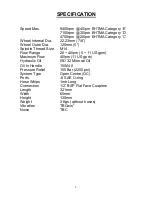
Page 4: ...Spindle Thread Size M14 Flow Range 20 40lpm 5 11 US gpm Maximum Flow 40lpm 11 US gpm Hydraulic Oil ISO 32 Mineral Oil Oil In Handle 15W 40 Pressure Relief 155 Bar 2250 psi System Type Open Centre OC...

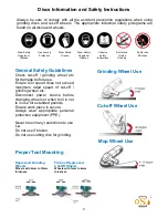
Page 5: ...ed for grinding sanding cutting and cleaning of metal and stone materials This Grinder should only be operated by competent trained operators WARNING SERIOUS INJURY OR DEATH COULD RESULT FROM THE IMPR...

Page 6: ...c for damage before use Ensure tool speed does not exceed maximum rated speed of cut off grinding wheel etc Disconnect power source before changing wheels or when tool is not is in use for extended pe...

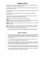
Page 7: ...uence of drugs alcohol on medication tired or feeling unwell as your judgement becomes impaired and could lead to serious injury or death not just to yourself but others around you You have a duty not...

Page 8: ...nvironment Hold the Angle Grinder firmly with both hands at all times whilst operating Do not overreach ensure you keep your balance and sure footing at all times Make sure that the work piece is secu...

Page 9: ...he wheel shatters Kickback occurs due to operator error and injury can be avoided by taking proper precautions and following the procedures listed Grip the Grinder firmly by the side handle and around...

Page 10: ...ntre OC type 3 Wipe the flat face couplings with a clean cloth 4 Connect the return hose first to the power pack and then the pressure hose When disconnecting uncouple the pressure hose first and the...

Page 11: ...housing 31 handle c w handle housing 20 27 10 Remove the two gears 30 38 Clamp the handle housing 27 in a vice and unscrew the handle 20 11 Remove circlip 42 and take out the seal housing 24 Split th...

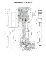
Page 12: ...GR05UW PARTS ILLUSTRATION 9...

Page 13: ...10...

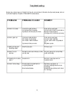
Page 14: ...hot Incorrect hydraulic flow Oil Cooler not working Oil Cooler matrix blocked Hydraulic Pump is worn Flow test power pack Check cooler electrics Clean matrix with compressed air Replace pump Leaking o...

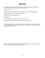
Page 15: ...parts fitted Rubber products Product subjected to misuse abuse or being neglected in any way Being modified in any way without prior written consent of E C Hopkins Ltd In case of disagreement between...

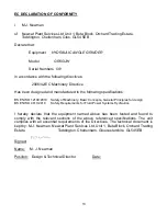
Page 16: ...010 Safety of Machinery Basic Concepts General Principles for design BS EN ISO 4413 2010 Safety Requirements for Fluid Power Systems Hydraulics I hereby declare that the equipment named above has been...

Page 17: ...x 2 5mm 12 200rpm Description Application Materials Part Number Size Max Rating 5 All Grind Diamond Grit Grinding Disc Durable Long Life with the ability to grind a wide range of materials General Gri...

Page 18: ...one Brick Construction Materials 322631 125mm x 2 4mm 12 200rpm Description Application Materials Part Number Size Max Rating Cup Wire Brush 100mm Crimped Steel Bristles General purpose cup wire brush...

Page 19: ...se silicon carbide grains Light Marine Growth Rust Paint removal Surface Preparation Various Inc Steel Stainless Steel Glass Fibre RSD30655 125mm DPC 12 000rpm Description Application Materials Part N...

Page 20: ...PKINS LTD UNIT 82 KETTLES WOOD DRIVE WOODGATE BUSINESS PARK BIRMINGHAM B32 3DB TEL NO 44 0 121 506 6095 FAX NO 44 0 121 421 8286 www echopkins co uk www underwatertools co uk enquiries echopkins bham...

Reviews: