background image


8/14 


3.Usage 


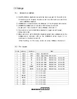
3‑1   Connection method 


① The HP3‑1500A is mounted on an external device as part of the controller.   

※From this point forward, the device will be referred to as controller 

with 1500#00‑A mounted.   

② 1500#00‑B is connected with the USB port of the Playstation3 console.  


③ 1500#00‑B communication indicator LED flashes on and off.   

(Light will turn on and off every 250msec intervals.) 

④ The controller with 1500#00‑A mounted is supplied with power.   

(DC+1.8V〜3.3V) 

⑤ When controller with 1500#00‑A mounted establishes communication the 

communication  indicator  LED  on  the  1500#00‑B  either  stays  lit  or 
continues to flashes on and off. 

(The flashing, in this case, occurs at every 100msec intervals.) 


3‑2  Pin layout 


Pin No 

Setting 

Function   

Note 

Input 

VSS 

Power  Ground(0V) 

Input 

VDD 

Power  Supply(DC+1.8V〜+3.3V) 

Input 

R2 

Inside pull‑down    Normal:Low    Active:Hi 

Input 

R1 

Inside pull‑down    Normal:Low    Active:Hi 

Input 

L2 

Inside pull‑down    Normal:Low    Active:Hi 

Input 

L1 

Inside pull‑down    Normal:Low    Active:Hi 

Input 

SELECT 

Inside pull‑down    Normal:Low    Active:Hi 

Input 

START 

Inside pull‑down    Normal:Low    Active:Hi 

Input 

− 

It is not used.   

10 

Input 

− 

It is not used.   

11 

Output 

− 

It is not used.   

12 

Output 

− 

It is not used.   

13 

Input 

− 

It is not used.   

14 

Input 

− 

It is not used.   

15 

Input 

− 

It is not used.   

Summary of Contents for 1500#00-A Series

Page 1: ...tion day reparation day reparation day reparation day 30 June 2009 30 June 2009 30 June 2009 30 June 2009 Product Name Product Name Product Name Product Name Model Name Model Name Model Name Model Nam...

Page 2: ...2 14 Revision hysteresis Date Edition number Revision content Writer 30 July 2009 First version First version publication T Ogawa...

Page 3: ...gence by the customer and damages due to abnormal use The company is not responsible for any incidental damage caused by our product loss of business loss of the business profit loss and or changes in...

Page 4: ...4 14 Contents Application range General specification Usage Radio specification Precautions for each standard Requirements to end product...

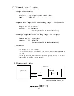
Page 5: ...dio module This is a transceiver module and requires it to be placed within an external input device to operate It must be used with model number 1500 00 B as a set 1 3 Application standard Wireless T...

Page 6: ...emperature and humidity range In storage Temperature 25 60 Humidity 20 85 RH Assuming there is no dew condensation 2 4 Function This product is a radio module It is necessary to set an external contro...

Page 7: ...n the presence of multiple Playstation3 a maximum 25 sets of 1500 00 A and 1500 00 B can be connected simultaneously 2 7 Power Input voltage DC 1 8 3 3V Supplied from 2 batteries Consumption current 5...

Page 8: ...tion indicator LED on the 1500 00 B either stays lit or continues to flashes on and off The flashing in this case occurs at every 100msec intervals 3 2 Pin layout Pin No Setting Function Note 1 Input...

Page 9: ...7 Output CSN It is not used 28 Input PS Inside pull down Normal Low Active Hi 29 Output MISO It is not used 30 Input Inside pull down Normal Low Active Hi 31 Output It is not used 32 Output MOSI It is...

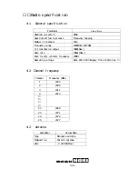
Page 10: ...y range 2405MHz 2477MHz IC transmission output 0dBm Max Data rate 1Mbps Max Rock crystal vibrator frequency 16MHz Operating voltage DC 1 8V 3 3V Supply from 2 batteries 4 2 Channel frequency Channel F...

Page 11: ...ver there is no guarantee that interference will not occur in a particular installation If this equipment does cause harmful interference to radio or television reception which can be determined by tu...

Page 12: ...th FCC IC RF exposure compliance requirements a separation distance of at least 20 cm must be maintained between the antenna of this device and all persons 2 This transmitter must not be co located or...

Page 13: ...nimum separation is maintained between users and the antenna 3 Co location This module must not be co located or operated in conjunction with any other antenna or transmitter The module integrator sha...

Page 14: ...se harmful interference to radio or television reception which can be determined by turning the equipment off and on the user is encouraged to try to correct the interference by one or more of the fol...

Reviews: