background image

15

VIVID32

OPERATING MANUAL

4.Operating Instructions

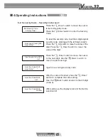
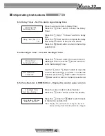
6-2. Security Code - Security code reset:

Press the“

Press the“

to item 2-Security Code.

Code.

Down” switch to move the cursor

Enter”switch to enter the Security

2.Security Code
3.Delay Timer

Up”switch to raise the value of the

Press the“

To reset the security code, input the 4-digit original

security code, starting with the left digit (code1).

digit. Press the“

value of the digit.

Down”switch to lower the 

Input Login Code:0000

Input Code 1

^

Press the“

to the next digit. Use the“

move to a previous digit.

Back” switch to 

Enter” switch to move the cursor

Input Login Code:0000

ok?

Input a new 4-digit security code.

Input Set Code:0000

Input Code 1

^

After the code is finished, press the“

switch to complete the code setting.

Enter”

Use the“

(code 4).

Back” switch to return to the 4th digit

Input Set Code:0000

ok?

After setting up, the display returns to the Set Up

selection list.

Input Set Code:0000

Confirm

Summary of Contents for VIVID32

Page 1: ...Fire Alarm Control Panel HORING LIH INDUSTRIAL CO LTD...

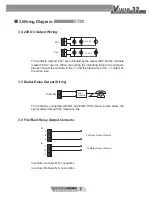
Page 2: ...3 4 24V DC Output Wiring 3 5 Dialler Relay Output Wiring 3 6 Fire Fault Relay Output Contacts 3 7 AC Power Connection 3 8 Dip switch instruction 4 Operating Instructions 9 9 9 5 Maintenance Instructi...

Page 3: ...COM Fault Alarm NO NC COM output contact points 7 Two sets of sounder outputs 8 Automatic dialer output 9 LCD screen is 24 digit x 2 lines 10 Long term and temporary mute silence feature 11 Sounder o...

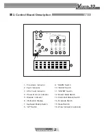
Page 4: ...h 8 UP Switch 9 DOWN Switch 10 BACK Switch 11 ENTER Switch 12 Buzzer Mute Switch 13 Alarm Bell Silence Switch 14 Evacuate Switch 15 Reset Switch 16 Zone Indicators optional 2 VIVID32 OPERATING MANUAL...

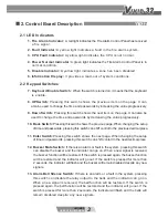
Page 5: ...page When changing the setup of time and passwords pressing this switch can shift control to the previous decimal place 11 Enter Switch Pressing this switch shows the next page When changing the setup...

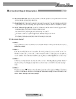
Page 6: ...es to input a 4 digit security code to enter LEVEL 3 in order to clear all memory data LEVEL 4 There is a screw form on the side of the panel door It requires a Phillips screwdriver to turn on to acce...

Page 7: ...SND1 AUX 24V DC DIALLER To Dialing Relay Output Device Indicating Lamp 24Vdc Output Sounder 24Vdc Output Dialler Output Fire Relay Output Fault Relay Output To Relay Output Device FIRE To Relay Outpu...

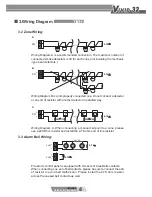
Page 8: ...of resistor with another detector in paralled way Wiring Diagram C When connecting a manual call point to a zone please use a 220 Ohm resistor and install the 4 7K ohm end of line resistor Fire alarm...

Page 9: ...wire to the contact at the same time The contact is connected with NO and COM When there is a fire alram the signal will go through the telephone line In picture A shows N O connection In picture B s...

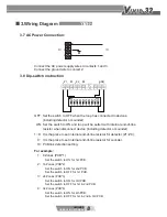
Page 10: ...al end of line resistor for detector Z1 Z8 9 It is the place to set internal end of line resistor for sounder 1 8 Zones PCB 1 Set the switch to ON for 1st PCB 2 16 Zones PCB 2 Set the switch to ON for...

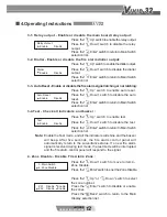
Page 11: ...1 16 38 58 1 All Status Disp 2 Memory Data Disp 1 Alarm Status Disp 2 Fault Status Disp Main Display 1 All status Disp 2 Memory Data Disp 3 Main Switch 4 Zone Disable 5 Memory Data Delete 6 Set Up 1 R...

Page 12: ...to Alarm Status Disp selection list 1 2 All Status Disp Check Fault Data 1 3 All Status Disp Check Disable Data 1 Alarm Status Disp 2 Fault Status Disp 2 Fault Status Disp 3 Disable Disp Zone Disable...

Page 13: ...to enter the Memory Data Disp Enter switch Down switch to move to item 2 Press the 3 Main Switch Switch selection list Press the Down switch to move to item Enter switch to enter the Main Press the t...

Page 14: ...elay Press the selection list Enter switch to return to Main Switch Press the output Up switch to enable the dialler output Press the Down switch to disable the dialler Press the selection list Enter...

Page 15: ...wer the value of the digit Down switch to move to item 5 Enter switch to move the cursor Enter switch to delete the memory Use the Back To delete the memory input a 4 digit code starting with the left...

Page 16: ...6 Edit Month After setting the month press the Enter switch to edit day Use the move to a previous digit Back switch to 2015 01 21 16 40 56 Edit Day After setting the day press the Use the digit Back...

Page 17: ...he left digit code1 digit Press the value of the digit Down switch to lower the Input Login Code 0000 Input Code 1 Press the to the next digit Use the move to a previous digit Back switch to Enter swi...

Page 18: ...o back Press the time setup and back to the previous screen Enter switch to complete the delay Enter switch to Enter switch Press the Up or Down switch to delay Up or Down switch to move the Press the...

Page 19: ...power supply of the fire alarm system the voltage of the backup battery and also discharge time of the backup battery Turn to the test mode to test if all the indicators can shine and buzzers can bee...

Page 20: ...which shouldn t give 24V DC reading If it meets the mentioned requirement please check the external wiring 4 Zone Abnormal Status Indicator ON According to the statistic most zone faults are due to i...

Page 21: ...ator will light up If you would like to make the Zone Faulty indicator go off you should install the end of line resistor across the L Z and LC Z contacts of the Zone After repairing the wiring please...

Page 22: ...nection Smoke Detector 30 Area Sounding Alarm Voltage 24V DC Maximum Supply Current 2A Fuse 2A Auto Reset Terminal Resistor 4 7K Relay Output Maximum Voltage 250V AC 30V DC Maximum Supply Current 2A A...

Page 23: ...Note...

Page 24: ...HORING LIH INDUSTRIAL CO LTD www horinglih com VIVID32 Operating Manual...

Reviews: