background image

Website: www.horizonglobal.com
Technical Assistance: 800-632-3290
TechnicalSupport@horizonglobal.com

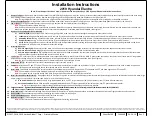
Installation Instructions

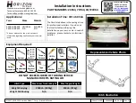
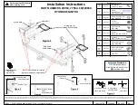
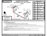
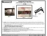
PART NUMBERS: 24964, 77964, CQT24964

©2017, 2018, 2019 Horizon Global™ Corp. –

Printed in Mexico  

Sheet 1 of 60

24964NP

06-24-19

Rev. C

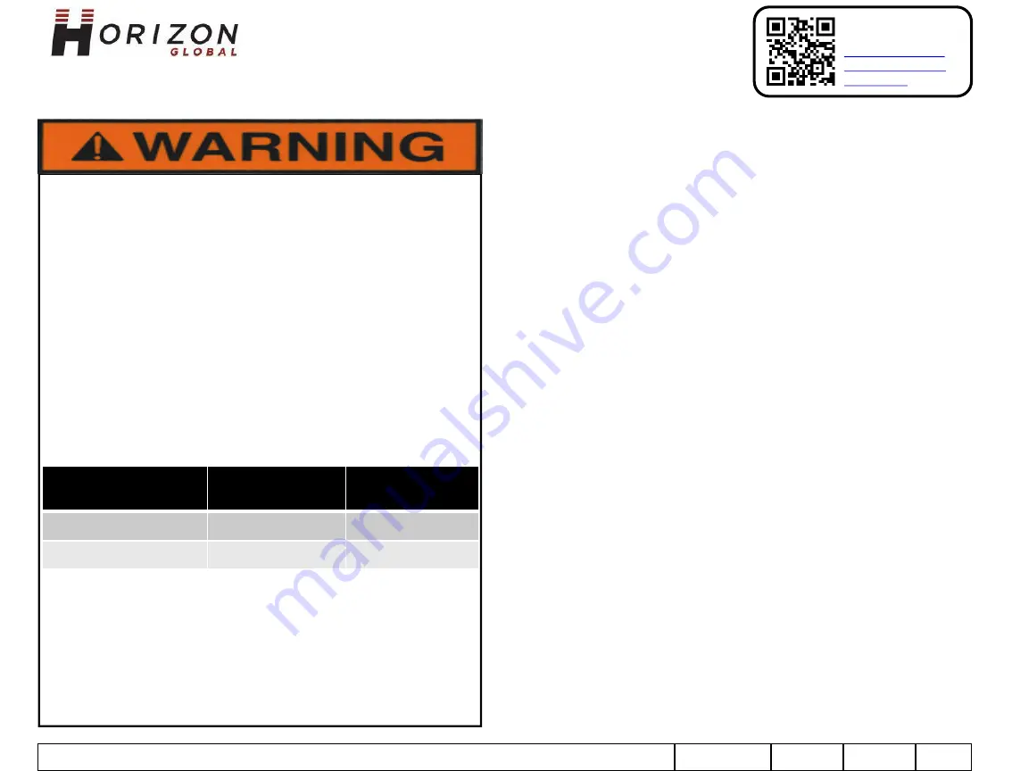
To prevent SERIOUS INJURY, DEATH or PROPERTY DAMAGE:

ALWAYS read, understand and follow warnings and instructions for  

your hitch BEFORE installation. Keep for future reference.

DO NOT cut, weld or modify this receiver.

CHECK all fasteners are tight and your hitch is securely mounted to 

your vehicle periodically.

ALWAYS read, understand and follow all warnings and instructions 

for your vehicle and for other accessories you will use with your 

hitch BEFORE use.

LOAD the trailer heavier in front.

DO NOT exceed lower of

towing vehicle manufacturer’s rating or:

ALWAYS wear your seatbelt.

SLOW DOWN when towing, NEVER exceed any posted speed limit.

If EXCESS SWAY occurs, take your foot off the gas pedal and hold 

the steering wheel as steady as possible. DO NOT apply your brakes 

and DO NOT speed up.

Hitch Type

Max Gross Trailer 

Weight

Max Tongue 

Weight

Weight Carrying

2000 Lb. (907 kg)

200 Lb. (91 kg)

Weight Distributing

N/A

N/A

LIMITED LIFETIME WARRANTY

1.

Limited Lifetime Warranty

(“Warranty”)

.

Horizon Global ("We",

“Us”

or

“Our”)

warrants to

the original consumer purchaser only ("You" or

“Your”)

that the product will be free from

material defects in both material and workmanship, ordinary wear and tear excepted. The
Warranty is valid only if: (a) the products are returned to Us for inspection and testing; (b)
Our inspection discloses to Our satisfaction that any alleged nonconformance are material
and have not been caused by misuse, neglect, wear and tear, improper installation,
unsuitable storage, improper repair, alteration, or accident; and (c) the products were
installed, maintained and used in accordance with Our instructions. THE WARRANTY IS
MADE IN LIEU OF ALL OTHER WARRANTIES, EXPRESS OR IMPLIED (OTHER THAN THE
WARRANTY OF TITLE AS PROVIDED BY THE UNIFORM COMMERCIAL CODE IN EFFECT IN
MICHIGAN), INCLUDING WITHOUT LIMITATION, ANY WARRANTIES OF MERCHANTABILITY
OR FITNESS FOR A PARTICULAR PURPOSE, SAID WARRANTIES BEING EXPRESSLY DISCLAIMED.

2.

Obligations of Purchaser.

To make a Warranty claim, contact Us at our principal address of

47912 Halyard Drive, Suite 100, Plymouth, MI 48170, 1-800-632-3290, identify the product
by model number, and follow the claim instructions that will be provided. Any returned
product that is replaced by Us becomes our property. You may be responsible for return
shipping costs. Please retain your purchase receipt to verify date of purchase and that You
are the original consumer purchaser. The product and the purchase receipt must be
provided to Us in order to process Your Warranty claim.

3.

Exclusive Remedy.

Product replacement is Your sole and exclusive remedy under this

Warranty. We shall not be liable for service or labor charges incurred in removing or
replacing a product. IN NO EVENT WILL WE BE RESPONSIBLE FOR ANY INDIRECT, SPECIAL,
CONSEQUENTIAL OR PUNITIVE DAMAGES.

4.

Assumption of Risk.

You acknowledge and agree that any use of the product for any

purpose other than the specified use(s) stated in the product instructions is at Your own risk.

5.

Governing Law.

This Warranty gives You specific legal rights, and You also may have other

rights which vary from state to state. This Warranty is governed by the laws of the State of
Michigan, without regard to rules pertaining to conflicts of law. The state courts located in
Oakland County, Michigan shall have exclusive jurisdiction for any disputes relating to this
Warranty.

Rev 8/2015

Scan for safe towing 
tip, or visit 

http://qr.towingpro
ducts.net/qrproduct
s/qr-product

Summary of Contents for 24964

Page 1: ...teration or accident and c the products were installed maintained and used in accordance with Our instructions THE WARRANTY IS MADE IN LIEU OF ALL OTHER WARRANTIES EXPRESS OR IMPLIED OTHER THAN THE WA...

Page 2: ...ibuting N A N A Representative Vehicle Photo 2017 2018 2019 Horizon Global Corp Printed in Mexico Sheet 2 of 60 24964NP 06 24 19 Rev C Installation Time 40 to 60 min The time listed above is the avera...

Page 3: ...y 6 Conical Washer 7 16 P N 01292007 Qty 2 Hex Nut 7 16 14 GR2 Qty 2 Fish Wire 7 16 P N 5481 o Qty 4 Hex Bolt M10 1 25 X 35mm CL10 9 p Qty 4 Hex Bolt M8 1 25 x 40mm CL10 9 q Qty 4 Conical Washer 3 8 P...

Page 4: ...supplied 10mm bolts item o 2 per side and 7 16 conical washers item l teeth side toward hitch b Korean built models Secure hitch to vehicle using supplied 8mm bolts item p 2 per side and 3 8 conical...

Page 5: ...d screwdriver remove 3 plastic push pins Then remove the plastic fascia attachment with a phillips head screwdriver 1 screw per attachment and return to owner 2 B Then remove the plastic fascia attach...

Page 6: ...Secure hitch to vehicle using supplied 10mm bolts item o 2 per side and 7 16 conical washers item l teeth side toward hitch b Korean built models Secure hitch to vehicle using supplied 8mm bolts item...

Page 7: ...Tighten all 8mm fasteners to 27 Lb Ft 37 N M all 10mm fasteners to 42 Lb Ft 57 N M and all 7 16 fasteners to 40 Lb Ft 68 N M Proper torque is needed to keep the hitch secure to the vehicle when towin...

Page 8: ...rk 5 long section perpendicular to edge of fascia Trim marked section from fascia to give clearance for the receiver tube of the hitch See Figure 3 Note Do not use middle support bracket hole for meas...

Page 9: ...ights are reinstalled on vehicle 2 Remove Underbody Panel Using a 10mm socket and flat head screwdriver remove 4 hex nuts and 3 push pin rivets from underbody panel on the driver s side of vehicle 3 L...

Page 10: ...ts holding bumper beam to end panel Repeat on other side of vehicle Return bolts to vehicle owner 4 B Fender Wells Using a phillips head screw driver remove 3 screws and one 8mm hex head screw from wh...

Page 11: ...from bumper beam and return to vehicle owner 5 A Disassemble Fascia Remove signal lights Remove 4 phillips screws unhook electrical connection disengage retention clip Set lamp assembly aside Repeat...

Page 12: ...er of fascia Mark 3 wide section centered on the center line of fascia Mark 5 long section perpendicular to edge of fascia Trim marked section from fascia to give clearance for the receiver tube of th...

Page 13: ...stall fascia and bumper assembly onto vehicle Hand tighten bolts to hold bumper and hitch in place Align and re engage all clips Reinstall all screws and push pin rivets removed from fascia a USA buil...

Page 14: ...Replace Underbody Cover Reinstall nuts and pushpins removed in Step 2 15 Reinstall Taillights Install taillights in reverse order of Step 1 Note Ensure filler panel is properly installed on each tail...

Page 15: ...and bumper beam assembly to vehicle Be sure to reconnect all wiring 7 Modify Heat Shield Bend edge of heat shield down near exhaust hanger area to allow hitch side arm to sit flat against bottom of fr...

Page 16: ...ia Reinstall lower fascia aligning tabs in lower fascia with upper fascia and snap into place 11 Reinstall Taillights and Wiring Using the original hardware reinstall taillights and reconnect wiring R...

Page 17: ...aillights Using a 10mm socket remove 4 hex nuts that secure taillights both sides Unplug the wiring and remove the taillights by gently pulling rearward Nuts Push Pins 3 A Remove Fascia and Bumper Bea...

Page 18: ...er edges near wheel wells while gently pulling rearward on the fascia Disconnect the wiring harness from fascia if present 4 Remove Lower Fascia from Upper Fascia Using a flat head screw driver remove...

Page 19: ...hers supplied 2 per side 8 B Install Hitch Using a drill bit and the hitch as a template drill a hole in bottom of frame at center of slot in hitch both sides Remove rubber plug from forward access ho...

Page 20: ...s removed in step 1 11 Reinstall Taillights and Wiring Using the original hardware reinstall taillights and reconnect wiring Reinstall small access panels 9 Trim Lower Fascia Using a tape measure mark...

Page 21: ...utilis s conform ment Nos instructions LA GARANTIE SE SUBSTITUE TOUTE AUTRE GARANTIE EXPRESSE OU IMPLICITE AUTRE QUE LA GARANTIE DE TITRE OFFERTE PAR LE CODE COMMERCIAL UNIFORME AU MICHIGAN Y COMPRIS...

Page 22: ...1kg R partition de charge N A N A Photo repr sentative du v hicule 2017 2018 2019 Horizon Global Corp Imprim au Mexique Feuille 22 de 60 24964NP 06 24 19 Rev C Dur e de l installation 40 to 60 min La...

Page 23: ...Fil de tirage 7 16 po Pi ce No 5481 o Qt 4 Boulon hexagonal M10 1 25 x 35mm CL10 9 p Qt 4 Boulon hexagonal M8 1 25 x 40mm CL10 9 q Qt 4 Rondelle conique 3 8 po Pi ce No 01292006 r Qty 4 Espaceur trou...

Page 24: ...article o deux 2 par c t et des rondelles coniques 7 16 po article l c t dent vers l attelage b Mod les fabriqu s en Cor e Fixer l attelage sur le v hicule l aide des boulons 8 mm fournis article p d...

Page 25: ...deux 2 vis une 1 par c t et l aide d un tournevis lame plate retirer trois 3 goupilles poussoirs en plastique 2 B Enlever ensuite les attaches de car nage en plastique l aide d un tournevis cruciform...

Page 26: ...aide des boulons 10 mm fournis article o deux 2 par c t et des rondelles coniques 7 16 po article l c t dent vers l attelage b Mod les fabriqu s en Cor e Fixer l attelage sur le v hicule l aide des bo...

Page 27: ...isserie 8 mm au couple de 27 lb pi 37 N m et toute la visserie 10 mm fasteners au couple de 42 lb pi 57 N m et toute la visserie 7 16 au couple de 50 lb pi 68 N m Un couple de serrage ad quat est esse...

Page 28: ...e D couper la section marqu e du car nage pour procurer un d gagement au tube r cepteur de l attelage Voir figure 3 Nota Ne pas utiliser le trou de bride de support du milieu pour mesurer le trou n es...

Page 29: ...re sur le v hicule 2 Retirer le panneau de soubassement l aide d une douille 10mm et d un tournevis lame plate retirer quatre 4 crous hexagonaux et trois 3 rivets poussoirs du panneau de soubassement...

Page 30: ...au panneau d extr mit R p ter de l autre c t du v hicule Remettre les boulons au propri taire du v hicule 4 B Compartiments d aile l aide d un tournevis t te cruciforme retirer trois 3 vis et une vis...

Page 31: ...are chocs et les remettre au propri taire 5 A D monter le car nage Enlever les feux de signalisation Retirer quatre 4 vis cruciformes d crocher la connexion lectrique d faire l attache de retenue Mett...

Page 32: ...la ligne de centre du car nage Marquer une section de 5 po de long perpendiculaire au bord du car nage D couper la section marqu e du car nage pour procurer un d gagement au tube r cepteur de l attela...

Page 33: ...ge pare chocs sur le v hicule Serrer les boulons la main pour maintenir le pare chocs et l attelage en place Aligner et rattacher toutes les attaches R installer les vis et les rivets poussoirs qui on...

Page 34: ...s crous et les rivets poussoirs retir s l tape 2 15 R installer les feux arri re Installer les feux arri re dans l ordre inverse de l tape 1 Nota S assurer que la garniture interstitielle est correcte...

Page 35: ...ge sup rieur R installer le car nage sup rieur et la poutre de pare chocs sur le v hicule S assurer de rebrancher tout le c blage 7 Modifier l cran thermique Courber le bord de l cran thermique vers l...

Page 36: ...ieur Voir la Figure 4 10 R installer le car nage inf rieur R installer le car nage inf rieur en alignant ses languettes sur le car nage sup rieur et encliqueter en place 11 R installer les feux arri r...

Page 37: ...mm retirer quatre 4 crous hexagonaux qui fixent le feu arri re des deux c t s D brancher le c blage et enlever les feux arri re en tirant vers l avant avec soin Des noisettes Punaises 3 A Enlever le...

Page 38: ...e tout en tirant avec soin le car nage vers l arri re D brancher le faisceau de fils du car nage s il est pr sent 4 Enlever le car nage inf rieur du car nage sup rieur l aide d un tournevis lame plate...

Page 39: ...ar c t Voir la Figure 1 8 B Installer l attelage l aide d un foret po et de l attelage comme gabarit percer un trou de po dans le bas du cadre au centre de la fente dans l attelage des deux c t s Reti...

Page 40: ...feux arri re et le c blage l aide de la quincaillerie d origine r installer les feux arri re et rebrancher le c blage R installer les petits panneaux d acc s 9 D couper le car nage inf rieur l aide d...

Page 41: ...lizados de acuerdo con nuestras instrucciones LA GARANT A REEMPLAZA CUALQUIER OTRA GARANT A EXPRESA O IMPL CITA EXCEPTO LA GARANT A DE T TULO SEG N LO ESTABLECE EL CODIGO COMERCIAL UNIFORME VIGENTE EN...

Page 42: ...i n de peso N A N A Foto que representa al veh culo 2017 2018 2019 Horizon Global Corp Impreso en M xico Hoja 42 de 60 24964NP 06 24 19 Rev C Tiempo de instalaci n 40 to 60 MIN El tiempo indicado ante...

Page 43: ...te Este producto cumple con las especificaciones y requisitos de seguridad para conectar dispositivos y sistemas de remolque del estado de Nueva York V E S C Regulaci n V 5 y SAE J684 2017 2018 2019 H...

Page 44: ...y arandelas c nicas de 7 16 pieza l los dientes hacia el enganche b Modelos fabricados en Corea Asegurar el enganche al veh culo usando los pernos de 8 mm suministrados pieza p 2 por lado y arandelas...

Page 45: ...asadores de presi n pl sticos A continuaci n retirar el accesorio de la fascia pl stica con un destornillador de estrella Phillips 1 tornillo por accesorio y devolver al propietario Ver Figura 4 2 B A...

Page 46: ...ilizando los pernos de 10 mm suministrados pieza o 2 por lado y arandelas c nicas de 7 16 pieza l los dientes hacia el enganche b Modelos fabricados en Corea Asegurar el enganche al veh culo usando lo...

Page 47: ...os fijadores de 8 mm a 27 Lb pies 37 N M y todos los fijadores de 10 mm a 42 Lb pies 57 N M y todos los fijadores de 7 16 a 50 Lb pies 68 N M Se necesita la torsi n adecuada para mantener el enganche...

Page 48: ...dicular al borde de la fascia Recortar la secci n marcada desde la fascia para dejar espacio para el tubo receptor del enganche Ver la Figura 3 Nota No utilizar el orificio del soporte de apoyo del me...

Page 49: ...s traseras en el veh culo 2 Quitar el panel inferior de la carrocer a Con un cubo de 10 mm y un destornillador de cabeza plana quitar 4 tuercas hexagonales y 3 remaches de presi n del panel inferior d...

Page 50: ...nal Repetir para el otro lado del veh culo Devolver los pernos al propietario del veh culo 4 B Cavidades del guardabarros Con un destornillador de estrella Phillips retirar los 3 tornillos y un tornil...

Page 51: ...pietario del veh culo 5 A Desmontar la fascia Quitar las luces direccionales Retirar 4 tornillos de estrella Phillips desconectar la conexi n el ctrica liberar el clip de retenci n Colocar el conjunto...

Page 52: ...nea central de la fascia Marcar la secci n de 5 de largo perpendicular al borde de la fascia Recortar la secci n marcada desde la fascia para dejar espacio para el tubo receptor del enganche Ver la Fi...

Page 53: ...culo Apretar a mano los pernos para mantener el parachoques y el enganche en su lugar Alinear y volver a activar todos los clips Volver a instalar todos los tornillos y los remaches de presi n que se...

Page 54: ...las tuercas y los pasadores de presi n que se quitaron en el Paso 2 15 Volver a instalar las luces traseras Instalar las luces traseras en el orden inverso del Paso 1 Nota Asegurarse de que el panel...

Page 55: ...superior Volver instalar la fascia superior y el ensamblaje del travesa o del parachoques en el veh culo Verificar que se vuelvan a conectar todos los cables 7 Modificar el protector de calor Doblar e...

Page 56: ...ar nage inf rieur Voir la Figure 4 10 R installer le car nage inf rieur R installer le car nage inf rieur en alignant ses languettes sur le car nage sup rieur et encliqueter en place 11 R installer le...

Page 57: ...las 4 tuercas hexagonales que sostienen la luz trasera ambos lados Desconectar los cables y quitar las luces traseras halando suavemente hacia atr s Nueces Alfileres 3 A Quitar el ensamblaje del trave...

Page 58: ...mientos de las ruedas mientras la fascia se hala suavemente hacia atr s Desconectar el arn s de cables de la fascia si est presente 4 Quitar la fascia inferior de la fascia superior Con un destornilla...

Page 59: ...oniques 3 8 po fournis deux 2 par c t Voir la Figure 1 8 B Installer l attelage l aide d un foret po et de l attelage comme gabarit percer un trou de po dans le bas du cadre au centre de la fente dans...

Page 60: ...eux arri re et le c blage l aide de la quincaillerie d origine r installer les feux arri re et rebrancher le c blage R installer les petits panneaux d acc s 9 D couper le car nage inf rieur l aide d u...

Reviews: