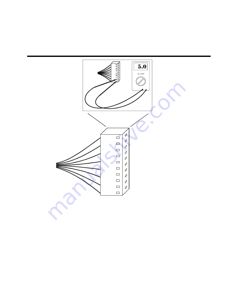
Console Cable Voltage Check (Programmable
Resistance)
- Imput from RPM Sensor
- Motor Ground
- Power to Photo-Optic Reset
- Power to Photo-Optic Count
- Power to Magnet Motor
- Power to Magnet Motor
- Input from RPM Sensor
- Power to Console
- Ground Wire
- Power to Console
- +
CORRECT VOLTAGE FOR WIRE HARNESS:
P1
PURPLE 0 VOLTS DC
P2
BLACK 0 VOLTS DC
P3
ORANGE 5 VOLTS DC
P4
BROWN 5 VOLTS DC
P5
GREEN .46 VOLTS DC
P6
WHITE .46 VOLTS DC
P7
YELLOW 5 VOLTS DC
P8
GREY 9.5 VOLTS DC
P9
BLUE 0 VOLTS DC
P10 RED 5.5 VOLTS DC
P1
P2
P3
P4
P5
P6
P7
P8
P9
P10
To check for voltages coming from a specific part (i.e. sensor wire, power supply, DC
motor), place the negative lead of the multimeter in pin P9 (ground) and the positive
lead in the desired pin. Follow the pin voltages listed above to diagnosis a specific
part. The power supply must be plugged into the power jack, and the console should
be plugged into the console cable to receive accurate readings.
34


