background image

(82)

OFF

ON

OFF

ON

7-2

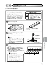
Installing the Control Panel

WARNING

Do not connect the power
cable before installing the
control panel. Install the
control panel only when the
power is OFF.

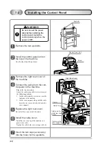
Remove the two eyebolts.

Install the control panel unit on
the top of the machine.

Use the four mounting screws.

Remove the right rear cover of
the machine.

Connect the cable from the con-
trol panel to the machine.

- Plug in the two connectors.
- Attach the cable using cable ties (accessory) at

the following positions:
1. On the cable from the area sensor, near the

top frame of the machine.

2. On the cover support, along with the cable

from the area sensor (already tied onto the
cover support.)

Replace the right rear cover.

Do not let the cover pinch the cable.

Install the cable cover.

- Install the cover on top of the machine so it

protects the cable.

- Tighten the cable to the cover using a cable tie.

Insert the two caps (accessory)
into the holes for the eyebolts.

Eyebolts

Screw

Right Rear Cover

Tighten on the
cable from area
sensor

Connectors

Screw

Control Panel Unit

Cable Tie

Tighten on the
cover support

Cable Cover

Summary of Contents for APC-61 II

Page 1: ......

Page 2: ...oper or inadequate maintenance by the customer unauthorized modification or misuse or operation outside of the environmental specifications for the product Horizon International Inc follows a policy o...

Page 3: ...ational Inc cannot anticipate every possible situation that might involve a potential hazard Therefore the instructions in this manual and the warning labels on the machine are not all inclusive All e...

Page 4: ...this training should not operate the machine Before starting the machine be sure to perform the checks described in Chapter 2 Safety Checks When loading the sheets on the table and setting the sheet...

Page 5: ...1 2 9 Maintenance Knife Replacement Screen 10 1 2 10 Maintenance Lubrication Screen 11 1 2 11 Maintenance Push out Length Setting Screen 12 1 2 12 Maintenance Clamp Pressure Adjustment Screen 13 1 2 1...

Page 6: ...et 59 5 2 There Is a Scratched Line On the Cutting Face 59 5 3 The Sheets Are Not Cut Parallel 60 5 4 The Top Sheet Is Marked By the Clamp 60 5 5 The Sheets Are Contaminated With Grease 60 5 6 A Sheet...

Page 7: ...the Control Panel 82 7 3 Connecting the Power Cable 83 7 4 Adjusting the Hydraulic Pump to Match the Frequency Only for Machines Used in 400 V Area 85 8 Appendix 87 8 1 Intended Use 87 8 2 Specificati...

Page 8: ...e backgauge moves forward by 0 1 mm When this button is pressed and held the backgauge keeps moving forward Backward Button Each time this button is pressed the backgauge moves backward by 0 1 mm When...

Page 9: ...ing lever can be locked using this screw Knife Angle Adjusting Lever The knife angle can be adjusted with this lever to get an even cut Foot Pedal Step on this pedal to lower the paper clamp Cutting D...

Page 10: ...g the length and other settings and store it as a sequence of steps See pages 6 through 8 for details Compression Mode Use this mode to do a compression operation and reduce the bulk of the booklet us...

Page 11: ...ushed out by the backgauge after each cut The backgauge then returns to the set position mm inch ent The key switch must be ON to enter the value 1 2 2 Cutting Normal Cutting Screen Use this screen to...

Page 12: ...tton Each time this button is pressed the function changes calibration and push out repeat Step Indicator These indicate the type of information displayed below step number cut length and push out dis...

Page 13: ...cut they will be pushed out by the backgauge After the sheets are cut they will not be pushed out Repeat Button After cutting the sheets the program does not proceed to the next step and the backgauge...

Page 14: ...ed the current value is entered and the backgauge position for each step is calculated automatically Then the display goes back to the Memory Programming Screen Screen Back Button When this button is...

Page 15: ...o the Programming Screen Program Select Button This recalls the selected program Program Delete Button This deletes the selected program Program Store Button This stores the current settings into the...

Page 16: ...of the cutting buttons in the Compression Mode 1 When the both cutting buttons are pressed only the clamp lowers After one second or more even if the cutting buttons are released the clamp remains lo...

Page 17: ...on The screen goes back to the Maintenance Mode Screen Knife Cut Counter This indicates the number of cutting cycles counted since the knife was last replaced Knife Replacement Screen Maintenance Mode...

Page 18: ...ubricating the machine The positions which require lubrication are shown on this screen 1 2 Control Panel Screen Descriptions Maintenance Mode Screen Lubrication Screen Page 1 Lubrication Screen Page...

Page 19: ...so that they can be removed easily This is set to 50 mm 1 970 at the factory The setting is adjustable within the range of 20 mm 0 785 to 150 mm 5 905 1 2 Control Panel Screen Descriptions 1 2 1 2 Ba...

Page 20: ...tting buttons in the Pressure Adjustment Mode 1 When both cutting buttons are pressed only the clamp lowers Keep pressing both cutting buttons and read the pressure indicator If either button is relea...

Page 21: ...ate of the sensors and switches which are installed on the machine 1 2 Control Panel Screen Descriptions Monitor Screen Page 1 Monitor Screen Page 2 Monitor Screen Page 3 Maintenance Mode Screen Back...

Page 22: ...or This indicates the current home position value Home Position Button After the value for the home position has been replaced Enter button press the Home Position Button to move the backgauge to the...

Page 23: ...of a service call you might be asked for the ROM numbers 1 2 Control Panel Screen Descriptions 1 2 4 3 1 2 3 4 Control ROM Version This goes to the Service Mode This should only be used by service per...

Page 24: ...hine always perform the safety checks listed in this chapter Oil Check 2 1 Oil Check Oil Gauge Check the oil level Locate the oil gauge installed on the rear of the machine and check that there is eno...

Page 25: ...rn ON the key switch The Key Switch Screen will appear If the Key Switch Screen appears the power switch and the software are OK After turning ON the power switch if the Initializing Screen does not a...

Page 26: ...ife and clamp might be in the lowered position If so the knife and clamp may lift a little to return to the upper limit position The normal Cutting Screen will appear on the control panel The value in...

Page 27: ...eck the pressure If the clamp does not lower or lowers too slowly there is a problem with the hydraulic pressure unit Please notify us If the clamp pressure indicator is out of the specified range adj...

Page 28: ...Press and hold one cutting but ton and then press the other cutting button Check that the machine does not run The machine runs only when both cutting buttons are pressed at the same time within 0 5...

Page 29: ...s one cutting cycle Check that the machine does not start the next cutting cycle if the cutting buttons are kept pressed after the end of the first cutting cycle There should be just one cutting cycle...

Page 30: ...er 25 mm or 0 985 and press the ent button If the clamp support plate is installed the value 25 mm 0 985 can not be entered Remove the plate and replace it on the bracket on the rear of the machine Ch...

Page 31: ...n appears Enter 620 mm or 24 410 and press the ent button Check that the backgauge moves and the current length is shown as 620 mm or 24 410 If you notice any problem while checking the backgauge plea...

Page 32: ...e this mode to set up the various cutting programs cutting length and other set tings and store them Compression Mode Use this mode to do a compression operation reduce the bulk of a booklet using the...

Page 33: ...de On the Menu Screen press the button for the mode you want to select To go back to the Menu Screen from the other Maintenance Mode Screens press the Back button 3 1 Selecting the Control Panel Scree...

Page 34: ...tton The value will be entered 3 2 Entering a Value 186 3 Normal Cutting Screen Numeric Keypad Screen 400 0 390 0 400 0 During a cutting operation if you want to make the sheets longer or shorter than...

Page 35: ...utting length value Press the button then the tab Press the Cutting Length Input The Numeric Keypad Screen appears On that screen enter the number for the position where you want to place the backgaug...

Page 36: ...her button is released the knife will lift After completing a cutting cycle release the cutting buttons The machine does not begin the next cutting cycle even if you continue to press the buttons Lowe...

Page 37: ...30 This page is intentionally left blank...

Page 38: ...on the side of the electrical box Start by setting the backgauge a bit behind the final cutting position This makes it easier to adjust the backgauge into the correct final position Press the backgau...

Page 39: ...n can be checked more accurately The knife lowers in front of the clamp by 0 6 mm 0 024 Press both cutting buttons The machine cuts the sheets To prevent the sheets from moving during the cutting oper...

Page 40: ...put the cutting length on the screen On the Normal Cutting Screen press the Cutting Length Input area and input the value using the Numeric Keypad Sreen After entering the value press the ent button T...

Page 41: ...eets To prevent the sheets from moving during the cutting operation continue to step on the foot pedal to hold the clamp down Repeat steps from through After completing the last cut turn OFF the key s...

Page 42: ...ach cutting length to the program Section 4 3 2 Press the button The Programming Screen appears The setup for the first cut is displayed in the middle of the list The display for each step has four it...

Page 43: ...e is 65 mm to 620 mm 2 560 to 24 410 When a value of less than 25 mm 0 985 or 65 mm 2 560 is entered the ma chine judges that as the value for the cutting width of the repeat function step and the rep...

Page 44: ...right Repeat steps through and set up all of the steps 4 3 Creating a Cutting Program Creating a Cutting Program 00 05 520 0 100 0 06 5 6 1 6 2 6 3 6 4 Step 520 420 320 100 100 100 100 100 100 100 100...

Page 45: ...ram has already been stored for the selected program number the Overwrite OK Screen appears If it is OK to overwrite press the OK button A program number with a stored program turns gray Now the progr...

Page 46: ...in the middle of the list Each step has four items 1 The step number 2 The cutting length 3 The push out distance 4 Whether the step is repeated and how often it is used Three steps are shown on the...

Page 47: ...ator Press both cutting buttons at once to cut the sheets After cutting the cutting length is stored for the current step After the cutting length is stored the program goes to the next step automatic...

Page 48: ...y been stored for the selected program number the Overwrite OK Screen appears If it is OK to overwrite press the OK button A program number with a stored program turns gray Now the programming process...

Page 49: ...dy been stored here Black This program is currently selected 3 Press the button The Programming Screen appears and the recalled program and steps are shown on the screen Move the step to be corrected...

Page 50: ...number buttons have the following meanings White No program is stored Gray A program has already been stored here Black This program is currently selected 3 Press the button If a program has already b...

Page 51: ...tep will be inserted in front of step 16 Press the button The new step is inserted and the following steps move down by one step each On the screen shown to the right the original step 16 changes to s...

Page 52: ...it is OK to delete the step press the OK button Any deleted data can not be recalled Check carefully before pressing OK To cancel the delete function press the button The step in the middle of the lis...

Page 53: ...program is currently selected Press the button All of the data in the program will be deleted The program number itself will not be deleted The Delete OK Screen appears If it is OK to delete the prog...

Page 54: ...remaining sheets in five equal sections Create a program to trim the sheets See Section 4 3 1 Entering the Values to Create a Program Create a program that trims the sheet on all four sides Go to the...

Page 55: ...entered which would make the divided sheet length less than the minimum cutting length 25 mm 0 985 The machine can be controlled in step of 0 1 mm 0 004 Any left over areas of less than one decimal pl...

Page 56: ...m has already been stored for the selected program number the Overwrite OK Screen appears If it is OK to overwrite press the OK button A program number with a stored program turns gray Now the program...

Page 57: ...Keypad Screen press these buttons 5 5 0 ent When the C button is pressed the value is cleared to 0 Input 5 0 for Constant Width Input 2 Press the Constant Width Input 2 area On the Numeric Keypad Scre...

Page 58: ...Program Number Input area The Program Select Screen appears Select the program number on the Program Select Screen The colors of the program number buttons have the following meanings White No program...

Page 59: ...am Select Screen 2 Press the button on the Programming Screen The Program Cutting Screen appears The backgauge moves to the correct cutting length for the first step 3 Press the cutting buttons and st...

Page 60: ...anings White No program is stored Gray A program has already been stored here Black This program is currently selected 3 Press the button The Program Cutting Screen appears and the selected program an...

Page 61: ...klet so that the spine touches the backgauge Press both cutting buttons at once CAUTION Do not leave the machine with the cutting buttons pressed pressure on for a long time This will cause the hydrau...

Page 62: ...mp support plate When the clamp support plate is installed on the bracket the switch detects this and changes the minimum cutting length for the backgauge to 25 mm 0 985 When the clamp support plate i...

Page 63: ...on the rear of the clamp The clamp support plate will drop Pull the clamp support out from the bottom and remove it To remove the clamp support plate easily keep it level Place the clamp support plat...

Page 64: ...he Push out Length Input area on the screen On the Numeric Keypad Screen enter the push out length This is adjustable within a range of 20 mm to 150 mm 0 785 to 5 905 After entering the value press th...

Page 65: ...58 This page is intentionally left blank...

Page 66: ...he sheets have trapped some air If the sheets include air they may move when compressed Remove any air between the sheets before cutting The clamp pressure is too light so the sheets move Increase the...

Page 67: ...rease less often Extra grease leaks out here Top View Cause Remedy The sheets have not been aligned correctly by the backgauge Check that the sheets are aligned by the backgauge correctly The backgaug...

Page 68: ...ck See Section 6 1 Cutting Stick Replacement If the knife is worn out some sheets may remain uncut Replace the knife See Section 6 2 Knife Replacement The cutting depth is not adjusted correctly After...

Page 69: ...switch is turned ON immediately after it is turned OFF this error may occur Be sure to wait 10 seconds or more before turning ON the power switch again 1361 1362 1363 1851 Memory Error 1 Turn OFF the...

Page 70: ...eplace the cutting stick Each cutting stick can be used up to 8 times four faces and two surfaces per face If all of the faces have been used already replace the part with a new cutting stick Clean ou...

Page 71: ...ace to put the knife after removal It is very dangerous to put the knife on unstable place The knife may slip or drop Use the knife replacing tools accessories to replace the knife If the screw on the...

Page 72: ...dden when the knife is at the lower limit the lowest position Tighten this screw last when installing the knife 4 Knife replacement mode In a normal cutting operation each time both cutting buttons ar...

Page 73: ...h Press the button then the button The Knife Replacement Screen is displayed Press both cutting buttons at once The clamp lowers then the knife lowers and stops at the lower limit Turn OFF the key swi...

Page 74: ...in the grooves screws 3 and 6 Now there are five screws 1 2 4 5 and 7 holding the knife Insert the knife replacing tools into the holes for screws 3 and 6 WARNING Tighten the tools by hand as much as...

Page 75: ...3 Lower the tools slowly to the left downward along the grooves Now the knife can be removed from the knife holder 4 Remove the knife Be careful that the knife does not hit the machine Place the knif...

Page 76: ...o the knife holder 1 Be careful that the knife does not hit the machine 2 Fit the knife replacing tools into grooves 3 and 6 and lift the tools to the right and upward 3 Lift the tools to the top Turn...

Page 77: ...vel Tighten the locking screw for the knife angle adjusting lever using the Allen wrench Turn ON the key switch Press both cutting buttons at once The knife will lower and stop at the lower limit Ther...

Page 78: ...oth cutting buttons Just the knife will lift Turn OFF the key switch Tighten screw 1 at the far right To clear the cutting counter after replacing the knife press the C button Press the button then th...

Page 79: ...g buttons at the same time Check to see if the sheets are cut evenly If they are not the knife is installed on a slant Adjust the knife angle 1 Loosen the locking screw for the knife angle adjusting l...

Page 80: ...es by 0 2 mm 0 008 each time the dial is turned by one notch If the cutting depth is too deep this may shorten the life of the knife and cutting stick Repeat steps through and adjust the cutting depth...

Page 81: ...and stop at the lower limit Keep pressing both cutting but tons and read the clamp pressure indicator Read the value on the scale If the cutting buttons are released the indicator will return to 0 In...

Page 82: ...w value for the home position 1 Touch the lower window on the screen 2 On the Numeric Keypad Screen input the new value In this example if the sheet should be made longer by 1 mm input a value that is...

Page 83: ...e power switch is turned OFF Remove the backgauge cover Loosen the backgauge locking lever Turn the lever counterclockwise Use a 19 mm wrench accessory to loosen the locking nut on the angle adjusting...

Page 84: ...ounting screws Loosen the backgauge locking lever Use a 13 mm wrench accessory to loosen the lock nuts on parallel adjusting screws 1 and 2 Adjust the backgauge so that it is parallel Use the 13 mm wr...

Page 85: ...is produced by one motion of the lever of the grease gun Add oil to the lubrication cup on the rear of the backgauge Remove the backgauge window cover and apply accessory lubrication oil or ISO VG68 A...

Page 86: ...after purchase Remove the lower front cover six mounting screws and drain the oil from the tank inlet using a pump Add about 40 liters 10 5 gal of oil ISO VG32 through the tank inlet Check the oil ga...

Page 87: ...80 6 10 Cleaning the Cooling Fan Clean the cooling fan once a year If it is dirty the oil temperature rises and oil deteriorates quickly Cooling Fan...

Page 88: ...When moving the machine do not hold onto the cover for the backgauge motor This may damage the ma chine Do not place anything in front of the cooling fan This may damage the machine Place the machine...

Page 89: ...able ties accessory at the following positions 1 On the cable from the area sensor near the top frame of the machine 2 On the cover support along with the cable from the area sensor already tied onto...

Page 90: ...ge the connection Install a circuit breaker The power consumption of the machine is about 3 1 kW Use a 15 A breaker Turn OFF the circuit breaker for the power board Connect the power cable to the powe...

Page 91: ...r the power board Exchange the positions of any two of the three black cables Do not move the yellow green cable Repeat steps through until the knife lowers when the cutting buttons are pressed ON 5A...

Page 92: ...e area of 60 Hz set the following CAUTION Be sure to turn the adjusting screw clockwise Remove the lower front cover Loosen the lock nut in the rotor pump section and turn the ad justing screw clockwi...

Page 93: ...86 This page is intentionally left blank...
Page 94: ...itioning 0 1mm 0 00393 Job Memory 99 steps 99 jobs total 3 000 steps Push out Length 20 to 150 mm 0 785 to 5 905 adjustable Cutting Speed 3 1 seconds T able Height 850 mm 33 5 3 Phase 200 V 50 60 Hz 3...

Page 95: ...ting screws for knife A950113 00 1 pc Grease Cartridge 4009667 00 1 pc Wrench 1 pc each Oil For lubricating backgauge A932676 00 1 pc Allen Wrenches 1 pc each Reversible Screwdriver 4005382 00 1 pc Sp...

Page 96: ...8 02 1 pc Wedges for Installation M013154 05 7 pcs Knife with Safety Cover C 61 1 pc Operation Manual and Parts Book 1 each Clamp Support Plate A950136 00 1 pc A P C 6 1 I I APC 61II GATHERER GATHERER...

Page 97: ...90 8 4 Consumables Grease Cartridge 4009667 00 1 pc Oil For lubricating backgauge A932676 00 1 pc Spare Knife C 61 1 pc Cutting Stick M013258 02 1 pc M013185 03...

Page 98: ...gth Indicator 5 28 Cutting Button 1 21 Cutting Depth Adjusting Dial 2 65 66 72 73 Cutting Length 6 37 39 Cutting Length Input 4 28 37 Cutting Stick 63 Cutting Mode 3 25 D Delete OK Screen 8 45 46 Divi...

Page 99: ...ing Screen 5 25 Program Delete Screen 46 Program Number 38 41 43 Program Select Screen 8 38 41 43 Programming Screen 6 35 Properties Screen 16 Push out 5 6 35 39 57 Push out Button 4 5 6 31 33 Push ou...

Reviews: