141
7
Inst
alling the Fore-
edge T
rim Section /
Inst
allation
7-2
Installing the Fore-edge Trim Section
1
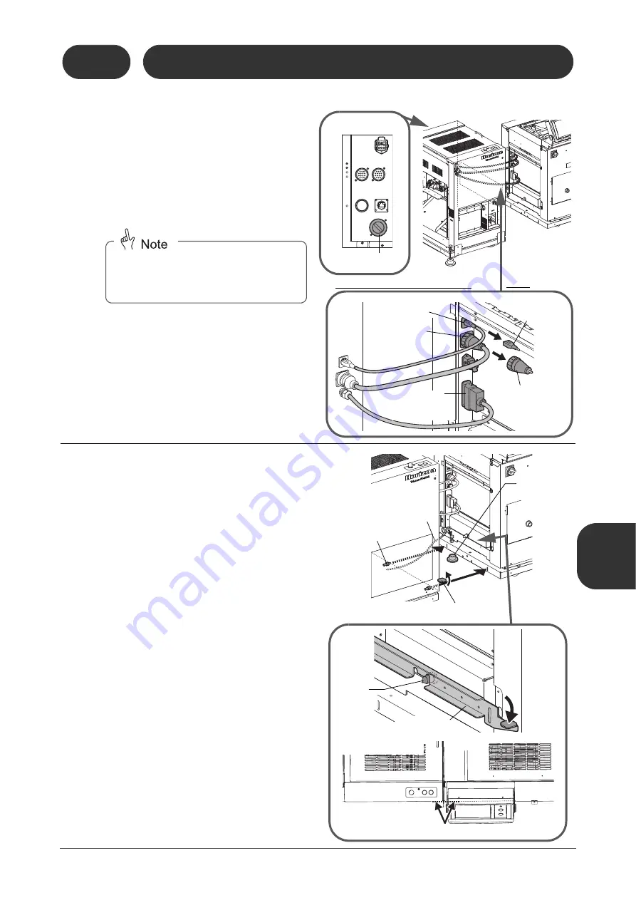
Connect the wiring between the
fore-edge trim section and the
main part of the SPF.
1. Remove the terminating connector and con-
nector for stand-alone machine from the
SPF main unit.
2. Connect the wiring as shown in the figure to
the right.
2
Hook the wire from the fore-edge
trim section on the SPF main unit.
3
Place the mounting plate in the
installation position.
4
Connect the fore-edge trim section
to the SPF main unit.
1. Raise the fore-edge trim section locking
lever.
2. Insert the positioning pins for the fore-edge
trim section to the slot on the SPF main unit
to make the connection.
3. Lower the locking lever and fit the locking
pin in the cutout on the lever.
- When the fore-edge trim section is lined up
with the SPF main unit, the locking pin will fit
into the cutout on the lever.
Attach the removed connector for stand-
alone machine into the socket on the rear of
the fore-edge trim section as shown in the
figure to the right.
11119
70201A1
11119
70201B1
Signal Connec-
tor for Fore-edge
Trim Section
Arcnet Communica-
tion Connector
Connector for
Stand-Alone
Machine
Connector for
Fore-edge Trim
Section
Fore-edge Trim Section
SPF
Terminating
Connector
11119
70201G1
Connector for Stand-
Alone Machine
Rear View
11119
70201C1
11119
70201D1
Wire
þ
Fore-edge Trim Section
Locking Lever
Locking
Pin
Locking Lever
Fore-edge Trim
Section
SPF
Overhead View
Lined up
Positioning Pin
Mounting
Plate (Large)
Summary of Contents for Bookletmaker FC-200A
Page 84: ...This page is intentionally left blank...
Page 94: ...This page is intentionally left blank...
Page 146: ...This page is intentionally left blank...
Page 202: ...This page is intentionally left blank...
Page 217: ...This page is intentionally left blank...
Page 218: ...Manufacturer Phone 81 75 934 6700 Fax 81 75 934 6708 www horizon co jp...


