background image

182

8-5

Mis-stitch Detector SDS-200

8-5-2  Operation

1

Set up the job on the Setting 
Screen and do the changeover.

The mis-stitch detector can be used in 
the range of sheet size as follows.

- Saddle Stitch and Fold Only

Max. : 356 mm x 508 mm (14.000” x 20.000”)      
Min. : 120 mm x 275* mm (4.725” x 10.827”)

Max. : 356 mm x 610 mm (14.000” x 24.000”)      
Min. : 120 mm x 275* mm (4.725” x 10.827”)

 *When the stitch distance is 195 mm or more 

(with the large saddle stitch stopper) or 150 
mm or more (with the small saddle stitch 
stopper),  the minimum length is 180mm.

- Top/Side Stitch

Max. : 356 mm x 380* mm (14.000” x 14.960”)  
Min. : 180 mm x 138 mm (7.090” x 5.435”)

  *When the stitch distance is 195 mm or more 

(with the large saddle stitch stopper) or 145 
mm or more (with the small saddle stitch 
stopper),  the maximum length is 432mm.

2

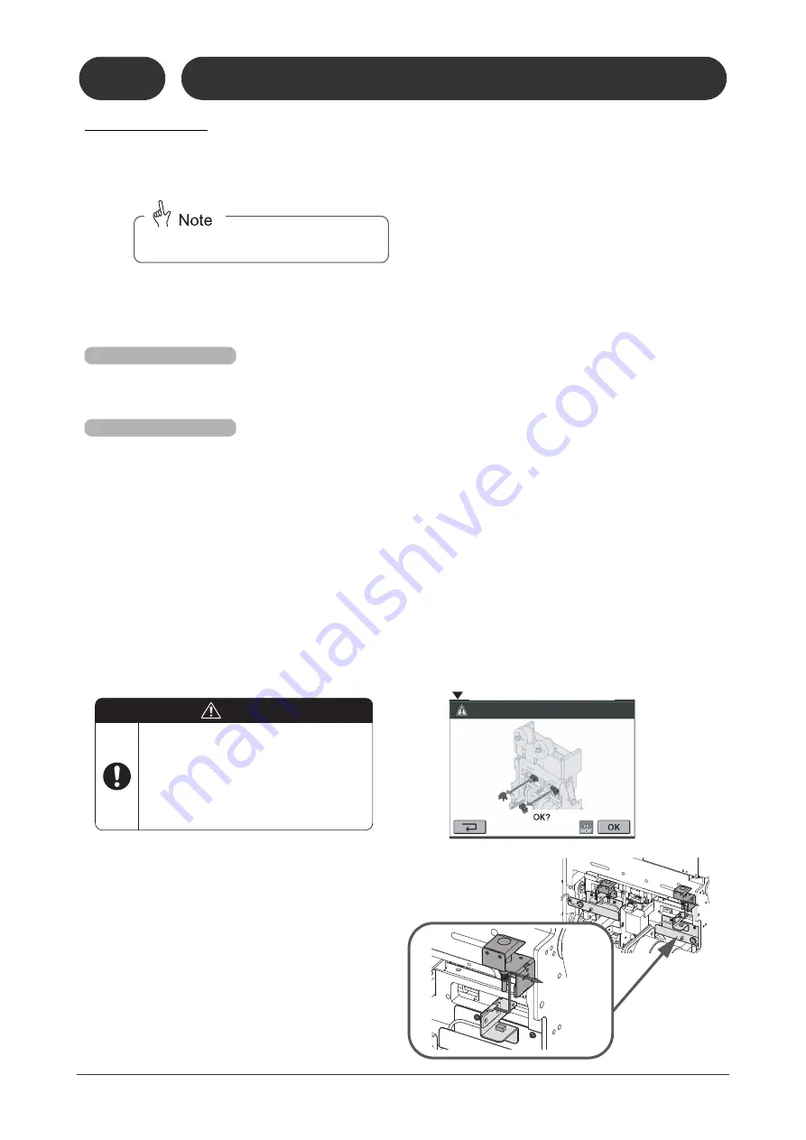
Install the sensor units as shown 
to the right so that the sensor 
comes behind the clincher.

3

Connect the connector of the sensor.

4

Start binding.

- The SDS-200 cannot be used in the corner 

stitching operation.

For the SPF-200A

For the SPF-200L

The sensor may hit the stopper depending 
on a binding pattern or a type of saddle 
stitch stopper (large or small). In case that 
the stitch detection is not available, the 
remove screen is displayed. Disconnect 
the connector of the sensor and remove 
the sensor from the magnet.

CAUTION

21102

80502C1

21102

80502D1

8-5-2

Operation

2110280501C1

Remove Screen

Summary of Contents for Bookletmaker FC-200A

Page 1: ...olicy of continuing improvement in design and performance of the product Therefore the product design and specifications are subject to change without prior notice and without our legal obligation All...

Page 2: ...ich includes important information Follow the note to operate the machine safely This symbol indicates a prohibited action Do not perform any prohibited action This symbol indicates an essential proce...

Page 3: ...oklets are delivered the machine will stop Do not allow anyone else near the machine when you are moving the main section of the SPF forwards or backwards When replacing the knife wear gloves and do n...

Page 4: ...thickness detector is installed evacuate the laser unit Otherwise the sensor may be damaged CAUTIONS for Maintenance Use the types of lubrication oil and grease which are recommended by HORIZON Other...

Page 5: ...creen 19 1 3 6 Binding Operation Screen 20 1 3 7 Binding Fine Adjust Screen 22 1 3 8 Binding Status Setting Screen 24 1 3 9 Memory Screen 28 1 3 10 Information Main Screen 29 1 3 11 Information Monito...

Page 6: ...h Position Varies 102 5 3 5 The Stitches Are Curved 102 5 3 6 There Are Problems With The Stitch Length 102 5 3 7 The Sheets Are Not Stitched 103 5 3 8 The Wire Jams 103 5 3 9 The Shape of the Stitch...

Page 7: ...placement 131 6 9 Stitcher Head Removal Attachment 132 6 9 1 Stitcher Head Removal 132 6 9 2 Stitcher Head Attachment 132 6 10Resetting the Circuit Breakers 136 6 11Replacing the Fuses 137 7 Installat...

Page 8: ...nstallation of Mis stitch Detector 179 8 5 2 Operation 182 8 6 Thickness Detector TD 200 183 8 6 1 Installation of Thickness Detector 183 8 6 2 Calibrating the TD 200 185 8 6 3 Operation 187 8 7 Chip...

Page 9: ...t Belt Gap Adjustment Transport Belt Height Adjustment Stopper Position Fold Roller Gap Jog Pusher Fold Section Top and Bottom Guide Width Fold Section Top and Bottom Guide Stroke Forward Roller Posit...

Page 10: ...system stops when a safety cover is opened or the Emergency Stop bottom is pressed dur ing operation 11119 10201A1 Jog Section Cover Fore edge Trim Section Cover Infeed Section Cover Emergency Stop Bu...

Page 11: ...and fore edge directions before folding This hap pens if the top and bottom guide jog function is turned on Infeed Section The sheets are trans ported from this section to the jog section Manual Feed...

Page 12: ...im Section Control Panel Transport Belt Not Used Hole for MKU 54 MKU 54T or PST 40 Com munication Cable Delivery Conveyor Option This illustration shows a short con veyor Connector for PK 30 Preset Ki...

Page 13: ...r is lowered Manual Feed Sheet Sensor This sensor detects any sheets placed on the manual feed table Manual Feed Guide This guide can be set to match the width of the sheet being fed Guide Position Sc...

Page 14: ...11119 10204D1 High Horizontal 11119 10204A1 Weights The transport roller pressure can be adjusted by changing the positions of these weights To move a weight turn the top to loosen it Hold down Guide...

Page 15: ...stitching Top and Bottom Guides These guides jog the sheets from the top and bot tom sides before stitching The settings listed below can be done using the touch panel Jogging frequency before stitchi...

Page 16: ...s displayed on the touch panel Coil Brake This brake prevents the coil from turning too easily and tangling the wire If the brake is pressed harder against the coil it becomes harder to turn the coil...

Page 17: ...can be adjusted on the touch panel Refer to 1 3 7 Sheet Hold Down Plate These plates prevent the sheets from floating Sheet Guide Locking Knobs If sheets jam between the fold rollers and press roller...

Page 18: ...urn the knob clockwise Jam Sensor Trim Knife Upper Knife Infeed Belts These belts move the sheet into the fore edge trim section Fore edge Trim Section Locking Lever If you are trimming small booklets...

Page 19: ...30 mm 1 2 from the end of the booklet Locking Knob Locking Knob Jog Button The conveyor belts move when this button is pressed Faulty Set Ejecting Tray When the faulty set eject function is activated...

Page 20: ...e machine they will be ejected While this is happening the button blinks When the machine is ready the button lights and feeding from the upstream device collator starts Machine Jog Button This jogs t...

Page 21: ...s one of these buttons for standard size sheets and the dimensions are entered automatically Press this button after entering the sheet size The Finishing Size screen next page is displayed Booklet Th...

Page 22: ...1119 10303C1 21102 10303A1 11119 10303B1 Finishing Size Saddle Stitch Screen Finishing Size Press one of these buttons for standard size sheets and the dimensions are entered automatically Stitch Type...

Page 23: ...om guides Attach the upper and lower parts for the top and bottom guides Remove the guide bars Replace the large saddle stitch stopper with the small one Replace the small saddle stitch stopper with t...

Page 24: ...inside Four stitch Two stitch Attach two stitcher head assemblies including the mounting block and the clincher inside Two stitch Four stitch Remove the sheet hold down plates in the fold section Mov...

Page 25: ...criptions If you press the following instruction screens appear The following screens below are displayed after the changeover Remove the stitch detection sensor Install the stitch detection sensor 11...

Page 26: ...ont stitcher head drive block Replace the front top and bottom guide with the corner stitch guides Remove the rear stitcher head drive block Replace the front corner stitch guide with the top and bott...

Page 27: ...to the selected sheet size are displayed here Hollow Area Under Corner Stitch Guide If the stitch heads are positioned outside the hollow area of the cor ner stitch guide This screen confirms the stit...

Page 28: ...unt When delivered booklets are offset the number of batch is displayed here To clear the batch count press Production Speed book per hour Maximum production speed differs depending on the binding typ...

Page 29: ...utton for the setting to be changed the Binding Status Setting screen is displayed Return to the Operation screen pXnet Screen The total binding count and the num bers of the remaining sets at startin...

Page 30: ...old knife and the forward roller 10 0 to 10 0mm 0 400 to 0 400 Maximum Fine Adjust Value 4 0mm 0 15 booklet thickness Booklet Thickness Fold Position Knife 21102 10307B1 Fine Adjust Fold Section Scree...

Page 31: ...thickness Finishing fore edge dimension 10 0 to 10 0 0 400 to 0 400 The default setting for the trim width is 3mm 0 125 Feed the sheets to the fore edge trim section Lower the transport belts Trim on...

Page 32: ...the specified time Manual Feed Setting No manual feeding Only manual feeding Using the HMU Hand Marry Unit on the collator This function cannot be selected from the screen It must be selected by usin...

Page 33: ...sheet adjust the waiting position using Stitch Section Top and Bottom Guide Stroke This sets the opening between the top and bottom guides when the sheets enter The default setting is 3 0 mm 0 120 Thi...

Page 34: ...n If you set this value smaller than the stitch section top and bottom guide delivery stroke its value is also reduced When Stitch Section Top and Bottom Guide Delivery Stroke is Off If you set this v...

Page 35: ...onal PN 200 Paper Inserter is installed Function not used Function used FC Booklet Thickness Detection Faulty set is detected by measuring the booklet thickness in the fore edge trim section These but...

Page 36: ...d without loading the job 21102 10309A1 Job No Input Enter the number of the job to be displayed using the numeric key pad screen which appears when this is pressed Job no 01 to 200 21102 10309D1 1 Bo...

Page 37: ...ce person only See next page 21102 10310B1 This is the total binding count since the machine was shipped This counter can be cleared in the Administrator Mode Use the counter as a guide for trim knife...

Page 38: ...110110311H1 Stepper Motor Lock Release If the is displayed you can move each guide and stopper by hand 2110210311B1 The input condition of each sensor signal can be monitored using these screens 21102...

Page 39: ...the counter Administrator Password Screen Press after the pass word is entered Trim Count The same trim count as on the Informa tion Counter screen is displayed here Information Counter Screen Wire Fe...

Page 40: ...one of the motors or sensors stops working the binding operation can be continued by turning off the broken motor or sensor If you want to turn off one of these motors contact a service technician for...

Page 41: ...ream down stream devices connected to the SPF 200A 200L Option Use this to selected the optional devices installed with the SPF 200A 200L SSK 200A SSK 200L SDS 200 PN 200 FST 200 PK 30 TD 200 TB 200 H...

Page 42: ...ct ing tray Jog section top and bottom guide or transport pusher overload The trim chute is full The stitcher head is not at the correct position Option The front wire is not stitched The rear wire is...

Page 43: ...30 HOF 20 is connected turn on the power switch for that also If the icon is displayed on the Initial screen it indicates that there is a problem with the system configuration settings Press to reset...

Page 44: ...ck the safety functions of the Emergency Stop buttons Press each Emergency Stop button The machine has two Emergency Stop but tons 5 SPF Main Unit Emergency Stop Button 6 Fore edge Trim Section Emerge...

Page 45: ...details 1 Turn On Power Refer to page 35 Chapter 2 Check Before Operating 2 Set Up Job Setting Screen Refer to page 39 Select the binding type Enter the sheet size Enter the finishing size 3 Do the C...

Page 46: ...port guide Use Not Used Faulty Set Ejecting Function On Off Wire Feeding Detection On Off Manual Feeding On Off Optional Device Settings 6 Start Binding Refer to page 62 Set the offset function Press...

Page 47: ...include detailed instructions for each part of the machine 1 Select the binding pattern Select the icon which indicates the required binding pattern The Sheet Size screen is displayed 21102 30201A1 R...

Page 48: ...0 4 725 OK 21102 30201B1 A A B B C C Sheet Size Screen Select one of these if you are using a standard size sheet 21102 30201C1 A A B B E E D D Sheet Size Screen HOF Error Icon No changeover is done...

Page 49: ...atterns except saddle stitching Press If the HOF error icon is displayed there is a problem with the HOF 20 30 Clear the error on the HOF 20 30 before trying to do the changeover The Setting Instructi...

Page 50: ...4 000 Min 85 0mm or 3 350 120 0mm or 4 725 11119 30201D1 Top and Bottom Finishing size On a machine set to measure in inches you must set the stitch distance carefully so the stitches do not hit the f...

Page 51: ...dures 3 3 2 Setting Up a Job Using the Setting Screen 5 Press The Setting Instruction screen is dis played If the HOF error icon is displayed there is a problem with the HOF 20 30 Clear the error on t...

Page 52: ...Parts Before the Changeover After removing the specified parts press 11119 30301B1 11119 30301C1 Guide Bar 11119 30301A1 Remove the guide bars in the jog section 11119 30301D1 Remove the upper and lo...

Page 53: ...locking screws press The stopper will move to a better location 11119 30301G1 Locking Screws Remove the sheet hold down plates in the fold section Once you remove the lock ing knob the plate can be r...

Page 54: ...46 3 3 Doing a Changeover If you press the following instruction screens appear Remove the stitch detection sensor Refer to Section 8 4 11119 10304K1 3 3 1 Removing Parts Before the Changeover...

Page 55: ...block Front corner stitching is optional Replace the front cor ner stitching guide with the top and bottom guides Attach the rear stitcher head drive block Replace the rear corner stitching guide wit...

Page 56: ...isplayed in the situations listed below because the machine does not know the current positions of the stitcher heads First changeover since the power was turned on If an Emergency Stop button is pres...

Page 57: ...the Guide 1 2 Tighten If you are using wide sheets the sheets may sag between the transport belt and the top and bottom guides If this happens attach the guide bar 11119 30302J1 Top and Bottom Guide...

Page 58: ...t hit the stopper and the trim posi tion varies adjust the position of the fore edge trim section You can make this adjustment also when the fore edge trim section is at normal position rear 1 Lift th...

Page 59: ...or corner stitching attach the sheet hold plate for side stitching if necessary This plate prevents the sheet from floating and going beyond the stopper There are no instruction screen to attach the...

Page 60: ...on Confirm that the guide gap is adjusted to match the booklet thickness Select from the three steps listed below When the thickness is 0 5 mm 0 020 or less Small 0 5 to 1 0 mm 0 020 to 0 039 Middle 1...

Page 61: ...ion 3 Attach the transport guide BC 20 1 Set the horizontal transport conveyor on the BC 20 to the horizontal position 2 Set up the faulty set ejecting function When you turn on the faulty set ejectin...

Page 62: ...een This can be selected when sheet width is 230 mm 9 05 or smaller 2 Load the sheets in the bins 3 Set up each section of the collator referring to Chapter 2 in the user s manual for the VAC 4 Do the...

Page 63: ...are fed from the upstream device then one booklet is deliv ered If the bound booklet is not delivered correctly or there is a problem with the binding quality go to Chapter 5 Troubleshooting If the d...

Page 64: ...uides or the stopper If there is a gap correct this A Distance between the jog plate and the stopper B Top and bottom guide width These items can be adjusted only while sheets are being jogged To test...

Page 65: ...jog pusher If there is a gap correct this C Distance between the fold knife and the jog pusher D Top and bottom guide width at fold sec tion These items can be adjusted only while the sheets are bein...

Page 66: ...ze E I E I 21102 30403E1 6 6 6 7 Binding Fine Adjust Fore edge Trim Section Screen If the gap between the booklet and the transport belt is too wide the booklet is bound and skewed when the booklet hi...

Page 67: ...of times to make the stitch The available range is 3 to 30 times 5 Press While the sheets are being moved they are stitched for the entered number of times When the stitch reaches within 10 mm 0 4 fr...

Page 68: ...icon No manual feeding Only manual feeding When the HMU is used Hand Marry Unit of the collator This function cannot be selected on the screen This function can only selected using a switch on the HMU...

Page 69: ...reen 7 Select the optional devices to use The default is for all of the optional devices to be turned off To restore to the default settings 1 Press The Confirmation screen is displayed 2 Press All th...

Page 70: ...to the touch panel VAC Start button on the remote control VAC Start button on the Main screen HOF 20 30 Start button on the control panel HOF 400 Start button on the Main screen If any sheets remain i...

Page 71: ...roblem There is a problem with the collator There is a problem with a down stream device The trim bin is full If the binding operation continue for one more minute feeding will stop Remove the trim If...

Page 72: ...e control panel HOF 400 Stop button on the Main screen Feeding stops and all processing booklets are bound and delivered The transport rollers keep rotating Press the Stop button again to stop the mac...

Page 73: ...l for the ST 40 for details When the HOF 20 HOF 30 is connected Set up the manual feed table and the front guide Refer to the user s manual for the HOF 20 HOF 30 for details When the HOF 400 is connec...

Page 74: ...slow This icon can be selected only if the IFU 200 is connected Sheets are fed manually to match the feeding from the collator Pro duction speed Fast This icon can be selected only if the IFU 200 is...

Page 75: ...switch 2 Press the Start button on the collator 3 Place the sheets on the manual feed table of the HMU If has been selected the sheet will be fed in one second after a sheet is placed on the manual f...

Page 76: ...beep 3 Insert a sheet in the manual feed section Push the sheet toward the manual feed stopper and hold it When the sensor detects the sheet the upstream device starts feeding The manual feed stopper...

Page 77: ...l feed stopper and hold it When the sensor detects the sheet the manual feed stopper moves down and the sheet on the manual feed section is fed Then the collated sheets from the upstream device is fed...

Page 78: ...s example the current job is saved in Job No 10 as job name BOOK 21102 30801A1 2 2 1 1 1 2 3 4 5 11119 30801B1 10 11119 30801C1 10 21102 30801D1 8 9 10 11 12 3 11119 30801E1 BOOK 21102 30801F1 10 BOOK...

Page 79: ...Main screen is displayed The job you selected is now loaded but the changeover has not been done yet 21102 30802E1 8 9 10 BOOK 06 06 10 11 12 4 21102 30802A1 2 2 1 1 1 2 3 4 5 Binding Operation Screen...

Page 80: ...ve to the saved positions If this is the first changeover since the power was turned on press All the job information is loaded not just the binding pattern and size data but also the fine adjustment...

Page 81: ...n screen is displayed 4 Press The Confirmation screen is displayed 5 Press The Memory Main screen is displayed The selected job is now deleted 21102 30802E1 8 9 10 BOOK 06 06 10 11 12 4 21102 30802A1...

Page 82: ...while the machine is in power saving mode 1 To return from power saving mode Touch the touch panel The Setting Finishing Size screen is dis played 2 Do a changeover When returning from the power savi...

Page 83: ...locked If this happens reverse the stitcher heads 1 Press the Stitcher Jog button while pressing the Machine Jog button Stitcher head returns to the original position by reverse movement 2 Remove the...

Page 84: ...This page is intentionally left blank...

Page 85: ...nob Stitch Balance Adjustment 1 Adjust the stitch balance by turn ing the adjusting wheel up or down Stitch Angle Adjustment 1 Turn the stitch angle adjusting knob 11119 40101B1 Shorten Wire Length Le...

Page 86: ...he wire does not feed check that the wire feed On Off knob is turned to the On position 3 Adjust the wire so that it comes out straight Adjust the angle of the eccentric shaft which feeds the wire 4 C...

Page 87: ...each weight in the correct direction 3 Turn each weight clockwise to lock it Infeed Section Direction Adjustment In the best setup the front edge of the sheet is directed toward the corner of the stop...

Page 88: ...and do not enter the top and bottom guides adjust the hold down guides Loosen the knob and adjust the height of each guide Sheet Holder Adjustment This guide holds the sheet on the belt if the tail of...

Page 89: ...locked position to match the booklet thickness Top and Bottom Guide Stroke Adjustment If the incoming sheet hits the top and bottom guides and jams increase the opening The default setting is 3 0 mm...

Page 90: ...played 3 Press The top and bottom guides move out The top and bottom guide becomes free to move manually 4 Loosen the mounting screws for the top and bottom guides on the front and rear 5 Move the top...

Page 91: ...oklet hold down plate To attach the plate hook it over the gate shaft The hold down plate works by pushing the sheet against the belts Remove the hold down plate if the sheet length is more than 400 m...

Page 92: ...e front and rear adjust the height of just the front transport belt to prevent the booklet from feeding crookedly Loosen the locking lever and turn the front trans port belt height adjusting knob cloc...

Page 93: ...from the upstream device to the fore edge trim section at a low speed the booklet may stop at the entrance of the fore edge trim section In this case narrow the gap of infeed belt How to Adjust 1 Loos...

Page 94: ...This page is intentionally left blank...

Page 95: ...ccurred in a downstream device Clear the error in the downstream device and press 2 130 151 155 156 Some sheets are jammed Open the cover remove the jammed sheets and press If this error occurs even t...

Page 96: ...r switch Check if the com munication cable between the devices is connected correctly then turn on the power switch again 14 No sheets for manual feeding were loaded in time to be fed Press and load t...

Page 97: ...ction to match the feed timing from the upstream device A jog error has occurred in the fold section If the sheets are not arranged correctly in the stitch section increase the jogging frequency using...

Page 98: ...Jam Cause and Solution 100 Upstream Device Com munication Error Check if the connector with the upstream device is connected to the SPF 200A 200L correctly and that the upstream device is powered on 1...

Page 99: ...r to Section 3 5 step 4 On the Administrator Mode screen set the number of times the machine can miss a stitch before this error is detected Refer to page 31 136 Jog Section Transport Belt Step out Th...

Page 100: ...pped because the distance between the upper and lower infeed belts is too wide reduce the distance between the upper and lower infeed belts in the fore edge trim section Refer to Section 4 5 314 Fore...

Page 101: ...ody forward backward movement motor M02 on the Information Single Operation screen If the body does not move fuse F02 may be blown Replace the fuse Refer to Section 6 11 If the fuse is OK please call...

Page 102: ...tactor Fault There is a problem with the interlock contactor K00 Please call your local dealer 1301 Inverter Alarm Turn off the power switch and wait about 10 minutes then turn it on again If the prob...

Page 103: ...sition and it may interfere with other moving parts This error will not be displayed again as long as the machine is homed again The binding operation can be continued temporarily but the booklet qual...

Page 104: ...et quality is not guaranteed 4145 M45 Fold Section Jog Pusher Home Position ing Error Please call your local dealer After you press OK to correct the error the machine will do a changeover At this poi...

Page 105: ...ss OK to correct the error the machine will do a changeover At this point the transport belt is not at the correct position and it may interfere with other moving parts This error will not be displaye...

Page 106: ...ain If the problem occurs again please call your local dealer 8203 HP 200A EEPROM Error An EEPROM error occurred Please call your local dealer 8300 to 8399 Fore edge Trim Section and CPU Runaway Cause...

Page 107: ...he sheets press the Machine Jog button again to return the top and bot tom guides to the previous positions Sheets inside the buckle cannot be removed 1 Press the Emergency Stop button 2 Open the fold...

Page 108: ...guide Removing jammed sheets at the entrance of the fore edge trim section 1 Open the cover 2 Press down on the handle of the infeed belt unit to release the handle from the hook 3 Lift the infeed bel...

Page 109: ...itching and the stitches are moved parallel to the fold line the folding position may be incorrect Set the fold position correctly Where to Check Cause and Solution Related Item Make a fine adjustment...

Page 110: ...plate and the stopper B Top and bottom guide width 3 4 3 Where to Check Cause and Solution Related Item When doing saddle stitching The fold position changes Check if the folding position changes Go...

Page 111: ...pressed against the coils too tightly Loosen the coil brakes a little 1 2 6 The wire is tan gled or has run out Straighten out the wire if it is tangled If the wire is tangled inside the stitcher hea...

Page 112: ...egs must be the same length Adjust the balance so that the right and left stitch legs are equal 4 1 The clincher box must be aligned with the bender Install the clincher so that the cen ter of the ben...

Page 113: ...ger or thicker The wire must be straight Adjust the angle of the eccentric shaft so that the wire is fed straight 4 1 The wire must be straight Adjust the angle of the eccentric shaft so that the wire...

Page 114: ...ed Item The wire must be straight Adjust the angle of the eccentric shaft so that the wire is fed straight 4 1 The former must be installed correctly The wire may not be fed because it does not go int...

Page 115: ...nt of overlap using the Main screen on the collator User s Manual for the Collator The machine must be installed on the mounting plates If the machine is installed temporarily on cast ers the frame of...

Page 116: ...all Increase the jogging frequency using the Bind ing Status Setting Collator Faulty Set Detect Manual Feed Stitch screen Page 24 The stitch delay time is too short Increase the stitch delay time usin...

Page 117: ...Fine Adjust Fold Section screen so that the jog pusher fits against the tail edge of the sheets while the sheets are being jogged 3 4 3 The fold delay time may be too short Increase the fold delay tim...

Page 118: ...cor rectly Adjust the distance between the fold knife and the stopper using the Binding Fine Adjust Fold Section screen 1 3 7 The jog pusher in the fold section must fit against to the sheets Adjust t...

Page 119: ...o narrow Set the buckle gap correctly to match the sheet thickness 3 3 3 Where to Check Cause and Solution Related Item The forward roller may move away from the sheets while the sheets are being jogg...

Page 120: ...the fore edge trim section to the front then lock it again 3 3 2 The booklet may expand by differ ent amounts at the top and bot tom To prevent the booklet from moving diagonally adjust the height of...

Page 121: ...damage the fold roller A damaged fold roller must be replaced Please call your local dealer The booklet thick ness must be entered correctly The gap between the fore edge belts is adjusted automatica...

Page 122: ...r rectly If the delivery conveyor is attached to a SPF 200A 200L check if the power connector for the delivery conveyor is connected correctly to the left side of the SPF 200A 200L If the delivery con...

Page 123: ...rcuit breaker has tripped wait a few minutes and then turn on the circuit breaker 6 10 Where to check Cause and Solution Related Item You may have tried to stitch an extremely thick booklet Reverse th...

Page 124: ...lution Related Item The delivery conveyor run distance for offset function is too short The first booklet in the one batch slips inside the last one in the previous batch Increase the delivery conveyo...

Page 125: ...stitcher heads 2 Hold the coils in place with the wire brakes Press each wire brake lightly against the wire coil to hold the wire coil in place When using thick wire No 24 and 25 you must use the op...

Page 126: ...stitcher heads and the clincher 2 Close the cover 3 Press and hold the Stitcher Inching button to make a stitch Take your finger off the button after finishing a stitch Check the sheet If the sheet is...

Page 127: ...paper jams If this happens mount the transport pusher 1 Turn off the power switch 2 Attach the transport pusher The transport belt can be moved freely when the power is turned off Hook the projection...

Page 128: ...e shaft with a waste cloth 3 Lubricate the slide shaft with oil accessory 6 4 3 Fold Knife Section Lubrication frequency once a month 1 Turn off the power switch 2 Add ten drops of oil into the lubri...

Page 129: ...5 Clincher Drive Cam Lubrication frequency once a month 1 Turn off the power switch 2 Apply grease to the cam shown in the figure to the right 11119 60404A1 1 3 5 7 L 0 2 hohner UNIVERSAL 43 6 S 11119...

Page 130: ...NING 11119 60501A1 When vacuuming keep away from the electrical cables CAUTION 21102 60502B1 11119 60502A1 11119 60502C1 Printing ink can transfer to the transport belts and rollers and can stain the...

Page 131: ...fore edge trim section from the SPF main unit and clean the reflector from the left side of the SPF main unit 11119 60503G1 Booklet Stopper Reflector Stitch Section Sheet Detect Sensor Infeed Conveyor...

Page 132: ...3A1 11119 60503I1 11119 60503I1 Faulty Set Detect Sensor Loosen the two screws to remove the sensor attachment support before cleaning Reflector Faulty Set Detect Sensor Sensor Attachment Support Clea...

Page 133: ...Jog button and raise the upper knife as far as possible Now press plate is raised 3 Separate the fore edge trim sec tion from the SPF When replacing the knife wear gloves and do not touch the edge of...

Page 134: ...102 60601E1 21102 60601D1 4 4 4 4 4 5 5 5 5 5 5 5 5 Use the handle to hold the upper knife Upper Knife Pipe Bracket Do not try to use a resharpened knife which is shorter than about 58 5 mm 2 31 CAUTI...

Page 135: ...ife Temporarily tighten only the outside mount ing screws while pressing them against the trim base Leave the inside mounting screws loose 6 Attach the upper knife 7 Turn on the power switch for the m...

Page 136: ...the adjuster bolts against the lower knife Stop when the adjuster bolts are just touch ing the knife 11 Place a piece of paper under the upper knife Press the Trim Knife Reverse Jog button return the...

Page 137: ...back to step 11 and repeat the steps again 14 Turn off the power switch 15 Lock the lower knife and the adjuster bolt Tighten the inside mounting screws with a ratchet wrench Tighten the mounting scre...

Page 138: ...gn the clincher with the stitcher head Use the positioning gauge in the accesso ries Refer to section 6 9 for using the positioning gauge 11119 60701A1 11119 60701B1 Pusher 11119 60701C1 Be careful no...

Page 139: ...lacement If the upper and lower sections of the top and bot tom guides are not removed before changeover to a small size setting the guide sheet may be dam aged If this happens replace the guide sheet...

Page 140: ...tcher head Attach the detection bar to the stitcher head on the operator side only Screw the detection bar into the screw hole on the block Set the detection bar height at about 82 mm or 3 23 4 Attach...

Page 141: ...e feed On Off knob to the Off position 7 Close the cover and press the stitch jog button to stop the bender at the lower position Lock the bender where it is raised 1 to 2mm from the lowest position 1...

Page 142: ...Close the cover 3 Press and hold the Stitcher Inching button to make a stitch Take your finger off the button after finishing a stitch Check the sheet If the sheet is not stitched repeat steps 1 to 3...

Page 143: ...ght 14 Check that there is a gap of about 1 mm 0 04 between the screw head and the proximity sensor If the gap is not correct loosen the block locking screw and adjust the angle of the block 11119 609...

Page 144: ...n on the breaker after waiting a few minutes Push down the switch first and return it to the original position to turn it on 6 Attach the breaker cover Turn off the power switch before resetting any c...

Page 145: ...oard QPW 757 4102 8300 Fuse F1 on the Fore edge Trim Knife Section Control Board QPM 237 Symptom Fuses The delivery conveyor does not move Fuse F60 on the SPF Power Board QPW 757 if the delivery conve...

Page 146: ...This page is intentionally left blank...

Page 147: ...in Unit Attach a rope to the four eyebolts on the corners and hoist the SPF 11119 70101C1 11119 70101D1 11119 70101G1 11119 70101F1 Screws for cover Locking Bracket Spacers Cap Screws 11119 70101E1 Ca...

Page 148: ...4 Place a mounting plate under each leveling bolt and turn the leveling bolt to lift the main unit up Lift the main unit so that all the casters have a space of 2 to 3 mm 0 08 to 0 12 to the floor 5...

Page 149: ...SPF main unit to make the connection 3 Lower the locking lever and fit the locking pin in the cutout on the lever When the fore edge trim section is lined up with the SPF main unit the locking pin wi...

Page 150: ...ere is no clearance raise the SPF main unit and then raise the fore edge trim section After making the adjustment lock each bolt using the lock nut If the SPF 200L has a torsion of frame make the foll...

Page 151: ...move the connector cover 3 Use a wire tie to attach the end of the cable from the main unit to the sensor bracket 4 Connect the sensor connector 5 Attach the connector cover Put any extra cable into t...

Page 152: ...ok the faulty set ejecting tray into the slot on the fore edge trim section 2 Attach the supports to the faulty set ejecting tray 3 Attach the faulty set ejecting tray using the screws 11119 70301E1 1...

Page 153: ...the hanger bolts into the holes 3 Attach the supports Use the screws already attached to the con veyor and main unit The supports can be attached by just loosing the screws 4 Attach the stack plate 5...

Page 154: ...bottom of the con veyor and tighten the screws 3 Install the conveyor To install the conveyor insert the hanger bolts into the holes on the conveyor Place the rail under the casters 4 Attach the stac...

Page 155: ...E1 Docking Plate Lower Cover Collator Delivery Section Collator Collator Height Refer to the user s manual for the collators for the height adjustment Match the height SPF 11119 70501G1 111191 70501H1...

Page 156: ...he HOF 400 AC 400 25 23 11119 70501J1 Noconnection here Lower Cover Match the height AC 400 Height Refer to the user s manual for the HOF 400 for height adjustment of the AC 400 and installa tion of t...

Page 157: ...11119 70501A1 111191 70501B1 No connection here Lower Cover Match the height HOF Height Refer to the user s manual for the HOF for the height adjustment HOF 30 HOF 20 SPF 11119 70501C1 111191 70501D1...

Page 158: ...0 or above Panel Image ROM VAC 60H IMG V 5 00 or above a tower S N 317001 m tower 319001 c tower 317001 or above the following machines are shipped with ROM V 5 00 or above ROM Name ROM Version Contro...

Page 159: ...or above are shipped with ROM V 5 00 or above 11119 70601F1 11119 70601G1 CON12 CON3 CON4 CON17 CON5 CON6 CON7 CON19 CON13 CON8 CON18 CON16 CON1 CON11 CON10 CON20 CON14 CON15 CON12 ROM DSW2 DSW DSW3...

Page 160: ...ibution panel 4 Turn on the power switch on the main unit Call an electrician when connecting the main unit power cable directly to the circuit breaker on the distribution panel in the building CAUTIO...

Page 161: ...ssword and then press the icon The Administrator screen is displayed 4 Press the icon The System Configuration screen is dis played 5 Press the buttons for each con nected device 6 Press the icon The...

Page 162: ...en is displayed 3 Press the buttons for the optional devices which are connected 4 Press the icon The setup is complete 21102 70801A1 21102 70801B1 Administrator Screen Option Screen Horizontal Transp...

Page 163: ...too much may cause unstable transportation of the sheets 3 Press the icon The Save screen is displayed 4 Press the icon The settings are saved and the Transport Speed Adjustment screen is displayed 5...

Page 164: ...ed and the Transport Speed Adjustment screen is displayed 8 Press the icon and then press the icon 9 Press the icon The Save screen is displayed 10 Press the The settings are saved and the Transport S...

Page 165: ...er 1 Install the preset kicker on the delivery conveyor as shown in the figure at right 2 Connect the cable of PK 30 to the connector on the rear of the fore edge trim section 3 Set up on the touch pa...

Page 166: ...n the touch panel 1 Press 2 Press and set up the number of booklets in a batch 3 Press to enter the value 3 Start binding After delivery of booklets in the preset num ber a booklet is skewed to separa...

Page 167: ...sher position on the Colla tor Faulty Set Detect Manual Feed Stitch screen The size of inserted sheets should be large enough to be brought to the transport pusher If it is too small the sheet cannot...

Page 168: ...with the stitch sec tion and prevent a booklet from being pulled while delivery when using single sheet or performing the job with folding only 6 Start binding If the transport pusher for paper insert...

Page 169: ...er on the SPF main unit 2 Replace the fold knife Loosen the mounting screws for fold knife from the frame hole shown in the figure at right Install the fold knife for paper inserter as shown in the fi...

Page 170: ...the alumi num stay 5 Install the aluminum stay to the main unit Fasten the screws temporarily at this step 11119 80202D1 Aluminum Stay Fasten the mounting screws while the bracket is lifted up Lift t...

Page 171: ...e plunger If the rollers can be lifted it is OK Fully tighten the screws on the aluminum stay at that point If the rollers are not lifted turn the aluminum stay to the direction B and lock it Repeat t...

Page 172: ...vice screen 1 Enter into the service mode 2 Press on the Service screen 3 Press 4 Press to go back to the Informa tion screen 21102 80201K1 Information Screen Service Screen Reset Idling Screen Enter...

Page 173: ...er Insertion Kit continued 9 Set up on the touch panel 1 Display the Administrator Mode Option screen 2 Press 3 Press to go back to the Information screen 21102 80201H1 21102 80201I1 21102 80201J1 Inf...

Page 174: ...Clincher Mounting Blocks 2 pcs Head Sliders 2 pcs 11119 80301A1 11119 80301B1 11119 80301C1 W16 W12 W8 11119 80301D1 11119 80301E1 Mounting Screws for attaching clincher on the mounting block 4 pcs M...

Page 175: ...it continued Head Guides 2 pcs Wire Feeding Detection Sensor Brackets 2 pcs Gauges 2 pcs Relay Wire 1 pc 11119 80301G1 Mounting Screws B4 8CRZP 4pcs 11119 80301H1 11119 80301I1 This gauge is used to p...

Page 176: ...ily These screws are fully tightened after align ing the clincher with the stitcher head in the step 5 on 8 3 4 6 Push down the clincher lever and check that the clincher points can be move up When th...

Page 177: ...e T shaped nut into the head slider 3 Fasten the locking screw for T shaped nut temporarily 2 Install the head guide to the stitcher head 3 Install the stitcher head to the main unit 11119 80303A1 Hea...

Page 178: ...the gauge against the rear face of the bender on the movable stitcher head Fully tighten the screw for T shaped nut after adjustment 5 Adjust the clincher position Align the clincher with the stitcher...

Page 179: ...the wire guide 3 Install the wire guide to the wire tube 4 Remove the stitcher head covers on the front side and rear side Each cover can be removed only by loosen ing a single mounting screw 5 Remov...

Page 180: ...e screw toward the direction A Check that the sensor is not On when the wire guide is pushed down and touches the screw head 2 Pull the screw to the direction B Pull the screw until the sensor just tu...

Page 181: ...ing Kit FST 200 8 3 5 Option Setup 1 Display the Administrator Mode Option screen 2 Press 3 Press and go back to the Information screen 21102 80201H1 21102 80201I1 21102 80305A1 Information Screen Adm...

Page 182: ...he outside stitch 190 mm 7 485 for 11119 80306C1 11119 80306A1 21102 80306B1 Minimum sheet width for four stitching Finishing Size Screen Minimum distance Fixed in 80 mm 3 150 190 mm 7 485 for 270 0 m...

Page 183: ...pulley shaft out to the rear 4 Assemble the drive shaft to the horizontal transport unit as shown in the figure at right Belt Tension Draw lines on the belt in 100 mm distance and tense the belt so th...

Page 184: ...Match the screw with the ditch of the shaft to lock the bearing 7 Lock the gas spring Install the gas spring on the pulley shaft of the side frame R and lock with the snap pin 21102 80401F1 21102 8040...

Page 185: ...talled 1 Remove the front cover of the fore edge trim section 2 Install the solenoid Fasten the cap screw with the shaft while the plunger is lifted up and the guide plate is lev eled 3 Connect the co...

Page 186: ...00L 8 4 2 Option Setup 1 Display the Administrator Mode Option screen 2 Press 3 Press and go back to the Information screen 21102 80201H1 21102 80201I1 21102 80305B1 Information Screen Administrator M...

Page 187: ...n ties 3 Attach two cable mounts on the position shown in the figure at right 4 Lead the cable as shown in the figure at right 2 Install the cable bracket Four units of SDS 200 cannot be installed for...

Page 188: ...t with nylon ties The mounting bracket moves laterally according to the stitch position Fasten the cable so that it cannot be stretched 5 Connect the front and rear connec tors 21102 80501E1 21102 805...

Page 189: ...plate 7 Set up on the touch panel 1 Display the Administrator Mode Option screen 2 Press SDS 200 3 Press to go back to the Information screen 11119 80401L1 Head Guide You can adjust the angle of brus...

Page 190: ...m x 138 mm 7 090 x 5 435 When the stitch distance is 195 mm or more with the large saddle stitch stopper or 145 mm or more with the small saddle stitch stopper the maximum length is 432mm 2 Install th...

Page 191: ...cover 3 Enter the short leg of a 5 mm Allen wrench into the hole of the middle clamp rod 4 Hold the clamp rod with the Allen wrench while removing the nut from the top 5 Replace the nut with the speci...

Page 192: ...the bush and lead it also through the bush of the electrical control box 12 Connect the cable at the lower part of the P C board 13 Fix the grounding wire to the frame Use an M4 screw and a tooth wash...

Page 193: ...Press TD 200 5 Press to go back to the Information screen 6 Display the Information Monitor FC screen and press the icon that appears under B200 The knife will lower automatically The display should...

Page 194: ...height of laser unit Adjust the brackets of the bar or the mount ing plate of the Laser unit until the value is within the correct range Point the laser beam in the center of the reflector 11119 80602...

Page 195: ...n is set 2 mm 0 08 wider than booklet length If the booklet is still trimmed adjust the stop per again 2 Turn on the thickness detector function on the Status Setting Option screen 3 Set the sensitivi...

Page 196: ...four booklets during operation The stored booklet thickness is cleared when the machine stops If misdetection occurs frequently the reflec tor may be dirty or the trim is attached to the clamp Wipe t...

Page 197: ...t the panel on the chip extractor 21102 80701A1 ON OFF 21102 80701B1 21102 80701C1 Air blows during operation Air blows while the breaker is turned on Breaker Power switch on the this unit Air flow ca...

Page 198: ...al of the TB 200 3 Connect the signal cable with the connector on the back of the fore edge trim section 4 Connect the power cable 21102 80602A1 Ground Terminal Connect to the groundingterminal for th...

Page 199: ...lation of Chip Extractor continued 5 Display the Administrator Mode Option screen 6 Press 7 Press and go back to the Information screen 21102 80201H1 21102 80201I1 21102 80702B1 Information Screen Adm...

Page 200: ...leased 6 Replace the standard bender with the type used for loop stitching Remove the standard bender and install the bender used for loop stitching Push the bender in and upwards Specifications of Lo...

Page 201: ...loop stitchinng the both two springs are necessary to install 9 Install the former used for loop stitching Then lower the spring plate 10 Install the stitcher head See Section 6 9 2 for installation S...

Page 202: ...This page is intentionally left blank...

Page 203: ...Top Stitch and Fold Max W 356 0 x L 216 0 mm 14 000 x 8 500 Min W 180 0 x L 90 0 mm 7 090 x 3 545 Corner Stitch Max W 326 0 x L 182 mm 12 820 x 7 165 Min W 210 0 x L 105 0 mm 8 270 x 4 135 Sheet Weig...

Page 204: ...er can be installed on the standard stitcher Production Speed Maximum 4 000 booklets per hour A4 Finish Portrait Maximum 4 500 booklets per hour A5 Finish Portrait Voltage Frequency Single Phase 200 t...

Page 205: ...SC 200 H705 27 8 810 31 9 4 420 174 1 670 26 4 665 26 2 1 625 64 0 1 460 57 5 SPF 200A H1 250 49 3 FC 200A H1 070 42 2 SC 200 H705 27 8 810 31 9 4 200 165 4 670 26 4 665 26 2 1 625 64 0 1 240 48 9 BC...

Page 206: ...klets per hour A4 Booklet Maximum 4 500 booklets per hour A5 Booklet Voltage Frequency Single Phase 200 to 240 V 50 60 Hz Rated Current FC 200A Single Phase 200 to 240 V 50 60 Hz 2 3 A Leak Current FC...

Page 207: ...Stitch Max W 356 0 x L 432 0 mm 14 000 x 17 000 Min W 180 0 x L 138 0 mm 7 090 x 5 435 Option Corner Stitch Max W 326 0 x L 364 0 mm 12 820 x 14 330 Min W 210 0 x L 210 0 mm 8 270 x 8 270 Option Pass...

Page 208: ...itching Wire Standard No 26 0 5 mm Option No 27 0 45 mm Wire of 0 4 to 0 6 mm diameter can be installed on the standard stitcher Production Speed Maximum 4 000 booklets per hour A4 Finish Portrait Max...

Page 209: ...hase 230 to 240 V 50 60 Hz 4 3 A Leak Current Single Phase 200 to 240 V 50 60 Hz 4 2 mA Heat Output SPF Main Body 2 830 kJ 680 kcal Delivery Conveyor SC LC 10 kJ 4 kcal Motors SPF Main Body 400 W x 1...

Page 210: ...50 49 3 SC 200 H705 27 8 SPF 200L H1 250 49 3 HOF 30 H945 37 3 LC 200 LC 200 LC 200 810 31 9 3 731 146 9 670 26 4 1 210 1 210 1 210 47 7 735 29 0 1 856 73 1 125 5 0 650 25 6 992 39 1 934 36 8 1 744 68...

Page 211: ...d Maximum 4 000 booklets per hour A4 Finish Portrait Maximum 3 500 booklets per hour A4 Finish Landscape Voltage Frequency Single Phase 200 to 240 V 50 60 Hz Rated Current FC 200L Single Phase 200 to...

Page 212: ...ie the cover Refer to Section 6 11 for details Signal Cable 1 pc each Hose 1 pc Sheet Hold Down Plates 2 pc each Stitcher Head Accessories 2 sets Hanger Bolts 2 pcs 11119 90201A1 11119 90201B1 11119 9...

Page 213: ...pc Pocket Caliper 1 pc Saddle Stitch Stopper Small 1 pc Transport Pushers 4 pcs Hold Down Plate for Small Booklets 1 pc Stopper for Touch Panel 1 pc 11119 90201N1 11119 90201O1 11119 90201P1 3 mm 1111...

Page 214: ...r Knife 1 pc Lower Knife 1 pc Spacer 2 pcs Trim Box 1 pc Socket Driver 1 pc 11119 90201C2 11119 90202K1 This connector is plugged to the SPF 200A 200L when shipped 11119 90202L1 This connector is plug...

Page 215: ...Cable No 12 1 pc LAN Cable 1 pc Drive Belt 1 pc Docking Plate 1 sheet Slide 1 pc 11119 90202K1 This connector is plugged to the Connector on back of the FC 200A 200L when shipped 11119 90202N1 This c...

Page 216: ...208 9 3 Consumables SPF 200A SPF 200L FC 200A FC 200L Grease Oil Wire Upper Knife Lower Knife 11119 90201T1 11119 90201U1 11119 90201C1 11119 90202E1 21102 90202F1...

Page 217: ...This page is intentionally left blank...

Page 218: ...Manufacturer Phone 81 75 934 6700 Fax 81 75 934 6708 www horizon co jp...

Reviews:

Related manuals for Bookletmaker FC-200A