background image

53

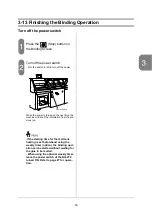
3-13 Finishing the Binding Operation

Turn off the power switch

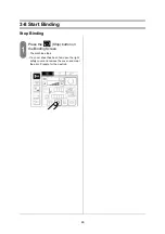
Press the 

 (Stop) button on 

the Binding Screen.

Turn off the power switch.

- Turn the switch to left to turn off the power.

When the power is turned on the next time, the 
machine will recall the information from the pre-
vious job.

-If the starting time for the melt tank 
heating is set beforehand using the 
weekly timer (option), the binding oper-
ation can be started without waiting for 
the glue to be melted.
- When using the optional weekly timer, 
leave the power switch of the BQ-270 
turned ON. Refer to page 97 for opera-
tion.

B

PERFECT BINDER

Power Switch

Summary of Contents for BQ-270

Page 1: ...nce by the customer unauthorized modification or misuse or operation outside of the environmental specifications for the product Horizon International Inc pursues a policy of continuing improvement in...

Page 2: ...h includes important information Follow the note to operate the machine safely This symbol indicates a prohibited action Do not perform any prohibited action This symbol indicates an essential procedu...

Page 3: ...nd install the machine safely and keep the weight of the unit in mind CAUTION When turning off the power switch and on again wait a dozen of seconds Otherwise the board may be damaged When the milling...

Page 4: ...16 Gluing Screen Part 3 17 Gluing Screen Part 4 17 2 2 Bind the Books Using the Binding Screens 18 Binding Screens 19 2 3 Test Milling and Gluing 20 Test Milling and Gluing Screen 20 2 4 Fine Adjustme...

Page 5: ...nging the Scoring Position 58 4 6 Changing the Carriage Clamp Opening and Milling Guide Width 58 4 7 Milling Depth Adjustment 59 4 8 Glue Temperature Adjustment 61 4 9 Side Glue Amount Adjustment Far...

Page 6: ...8 1 Installation 101 8 2 Installation of Extractor Option 104 8 3 Installation of Weekly Timer Option 106 9 Appendix 109 9 1 Specifications 109 9 2 Accessories 110 9 3 Consumable Parts 113 9 4 Option...

Page 7: ...g operation ON or OFF Turn the lever to the right to select milling ON Turn to the left to select milling OFF Delivery Section Stacks the bound booklets vertically Power Switch Touch Screen Used to in...

Page 8: ...ok blocks here aligning to the right Start Buttons When using the manual starting mode press both buttons to start the binding operation Grease Nipples Lubricate with grease here BQ 270 PERFECTBINDER...

Page 9: ...guide holds the book spine while the milling operation is done Guide Block This block transports the power from the motor to the front milling guide Brake Release Button This button is used when repl...

Page 10: ...o 180 248 to 356 Scrape Roller This roller scrapes the extra glue off of the spine Glue Supply Section Add more glue here when the glue level is low Lubrication Point Refer to 5 3 for details Applicat...

Page 11: ...side guide waits 3 mm 0 12 away from the edge of the sheet It registers the cover with the front side guide before the nipping operation Nipper Angle Adjusting Block Refer to 4 11 for details Registr...

Page 12: ...double feed stop pads If the pad is worn or double feeding occurs frequently raise the pads Refer to 4 14 for details Fixed Scoring Roller Scoring Roller Pressure Adjusting Knob Adjust to produce the...

Page 13: ...8 Touch Screen Push Plate This plate pushes the delivered booklets forward Stopper Set this stopper next to the push plate The stopper will be pushed forward as the booklets are stacked BQ 270 Touch S...

Page 14: ...ry job information Refer to 2 1 This screen is used to save or recall the job settings Refer to 2 5 These screens are used during maintenance cleaning or parts replacement They can also be used to che...

Page 15: ...Screens 2 Job Settings on Touch Screen Press the box and the Numeric Keypad Screen appears Input the setting value on the Numeric Keypad Screen in increments of 0 1mm 0 004 1 2 3 4 5 6 7 8 9 10 Bindi...

Page 16: ...must be set manually Binding without cover sheets Select when binding without cover sheets When this button is selected the side glue rollers should be moved out of their work ing positions Refer to 3...

Page 17: ...to a new set position Each part of the machine moves to the set position directly Select the start mode Normal Start mode Binding operation starts with start buttons Auto Start mode Binding operation...

Page 18: ...block thickness Measure the actual book block thickness using the attached caliper and input the value The input range is 0 3 to 50 mm 0 010 to 2 000 Input the book block length Measure the actual bo...

Page 19: ...the cover sheet width in increments of 0 1 mm 0 005 The input range is 135 0 to 320 0 mm 5 315 to 12 600 When measuring the distance to the center of the spine use the accessory alignment plate 4 1 2...

Page 20: ...ting Screens Function Screen ON Use the double feed detecting function OFF Do not use the double feed detecting function If the machine produces false indications of double feeding because of an image...

Page 21: ...page 59 2 1 Select this when doing milling The nipper raises then closes 2 2 Select this when nipping without milling The nipper closes as it raises to pre vent the spine from swelling If this mode i...

Page 22: ...ide glue will be applied If you select set the glue amount using the Gluing Screen Part 3 Side glue will not be applied Adjust the spine glue thickness in increments of 0 1mm 0 005 The adjustment rang...

Page 23: ...0 005 to 0 080 Adjust the wiper opening of application drum 2 Press once and the opening increases by 0 1 mm 0 005 More glue will be applied to the spine The adjustment range is 0 1 to 2 0 mm 0 005 t...

Page 24: ...10 9 8 7 6 5 4 3 2 Main Binding Screen Test Milling and Gluing Screen Clamp and Milling Fine Adjust Screen Glue Fine Adjust Screen Part 1 Glue Fine Adjust Screen Part 2 Glue Fine Adjust Screen Part 3...

Page 25: ...tton to lower the feed table Press this button to feed one cover sheet The machine memorizes the cover sheet thickness in order to detect the double feeding This button is used to stop the motor on ea...

Page 26: ...d check the applied glue amount Press start buttons to deliver the booklet Use this function to check the glue amount on the booklet Test Binding Button Press this button to perform a single binding w...

Page 27: ...hen using sheets which crease or tear easily Adjust the opening so that the book block can move into the carriage clamp easily without being disturbed After the adjustment check that there is enough c...

Page 28: ...range is 20 0 mm to 20 0 mm 0 785 to 0 785 This adjusts the end point for the spine glue The adjustment range is 20 0 mm to 20 0 mm 0 785 to 0 785 This adjusts the side gluing roller distance in incr...

Page 29: ...1 to 2 0 mm 0 005 to 0 080 This adjusts the wiper opening for application drum 2 Press once and the opening increases by 0 1 mm 0 005 More glue will be applied The adjustment range is 0 1 to 2 0 mm 0...

Page 30: ...er so that the glue will harden before the nipping operation If the glue squeezes out even if the nip ping delay time is increased decrease the spine glue thickness Nipping operating time The adjustme...

Page 31: ...fixed rollers actually do not move If the fixed scoring roller position is adjusted on the screen the stack of cover sheets actually moves to com pensate The adjustable scoring rollers move to the rea...

Page 32: ...the jog guides to their original positions Press the button to move the stack of sheets position to the right cover feeder side by 0 2 mm 0 008 The input range is 3 0 mm to 3 0 mm 0 110 to 0 110 This...

Page 33: ...ransport belts After the cover sheets are fed by the feed rotor the transport belts feed the covers back to the registration stopper The pressure of the transport belt is adjustable in five steps Norm...

Page 34: ...ct This sets the sensitivity of the double feeding detect sensor using high middle and low This sets the number of the window hole on the cover sheets The sensor which detects the window on the cover...

Page 35: ...ress the save button Press OK on the Write OK Screen and the present setting will be stored to the selected job number This is the read out or recall button Press the job number you want to read out t...

Page 36: ...elease the jammed booklet Carriage Clamp Close Carriage Clamp Open This triggers the booklet delivering motion the level plate moves back and the car riage clamp opens This is the Carriage Clamp Move...

Page 37: ...his moves the lower adjustable scoring roller to the set position Opens the milling guide to the limit Moves the milling guide to the set position Press this button once and the carriage clamp opens b...

Page 38: ...me position There are conditions which could cause part of the machine to lose its home posi tion This is the brake release button for the milling motor The milling motor can not be released by pressi...

Page 39: ...icated here The total binding number is indicated here The feed table is lowered when double feeding is detected The feed table is not lowered when double feeding is detected When changing the binding...

Page 40: ...e previous screen without entering a new value The cover is open Close the cover The emergency stop button is pressed Turn the emergency stop button clockwise Light between area sensors is blocked Rem...

Page 41: ...must work properly Operate the cover or press the button and check the error icons on the Error Screen If the Error Screen appears the safety function is working properly If the Error Screen does not...

Page 42: ...tall the shim If the support plate is not installed the bound book will fall on the stacker and separate Decide whether the machine should home all parts on every changeover and the starting mode Turn...

Page 43: ...th and width and the distance between the cover edge and the spine Refer to page 13 Turn the double feeding detect function ON or OFF Turn the double feeding detect function ON or OFF using the Functi...

Page 44: ...r sheet left on the nipper while changeover Remove the cover sheet and press OK If is pressed the changeover is canceled and the previous screen appears This screen appears when there is a book block...

Page 45: ...the screen and the milling lever set ting does not match Refer to page 37 to set the milling lever correctly and press OK If is pressed the changeover is canceled and the previ ous screen appears Thi...

Page 46: ...book blocks use a slower setting If you are binding a thick book block and the production speed is set too fast the milling can not be completed properly On the other hand if the pro duction speed is...

Page 47: ...een Part 2 The lower adjustable scoring roller moves next to the fixed scoring rollers Open the right safety cover Move the upper adjustable scoring roller by hand until it touches the fixed scoring r...

Page 48: ...ve the upper adjustable roller a bit with your finger Close the right safety cover Press the Setting Position button on the Single Operation Screen The adjustable scoring rollers move to the set ting...

Page 49: ...ing on each machine or other settings Set the desired glue thickness on the Gluing Screen Part 2 Perform the binding operation CAUTION The set position differs depending on the spine glue thickness se...

Page 50: ...e the side glue roller on the far side Before dislocating the roller make sure to memorize the original setting position Turn off the power switch and open the left safety cover To adjust the side glu...

Page 51: ...g operation Press both Start buttons WARNING Do not put your hand inside the machine when the carriage clamp is operating This part can cause severe personal injury When feeding a book block remove yo...

Page 52: ...rt Binding Stop Binding Press the Stop button on the Binding Screen The machine stops If a cover sheet has been fed open the right safety cover and remove the cover and clear the error Prepare for the...

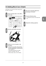
Page 53: ...able Separate the cover sheets well before stack ing If the cover sheets are not separated this can cause double feeding or the cover sheets may be partially fed If it is difficult to stack the cover...

Page 54: ...stacker is full Pull the stopper to the front Remove the stacked booklets Push the stopper to the rear WARNING Press the Emergency Stop button before removing the booklets If you do not do this the ma...

Page 55: ...using the Memory Screen Saving the Job Information Select the Memory Screen Select the job number on which you want to write the job information White Empty Gray Saved job Black Now selected Press the...

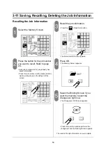
Page 56: ...ob number and the saved job infor mation will be shown in the left part of the screen Recall the job information Press the Read Out button The Read Out OK Screen appears Press OK The Memory Screen app...

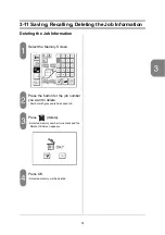
Page 57: ...g the Job Information Select the Memory Screen Press the button for the job number you want to delete Number with gray scale has saved job Press delete Selected memory number turns black and the Delet...

Page 58: ...f the glue level comes lower than the plate it may dam age the gluing mechanism Be careful that the glue level will not go over the upper limit line when the glue is melted This will cause the glue to...

Page 59: ...ned on the next time the machine will recall the information from the pre vious job If the starting time for the melt tank heating is set beforehand using the weekly timer option the binding oper atio...

Page 60: ...54...

Page 61: ...er to pages 22 and 23 4 2 Adjusting the Side Glue Amount If too much or too little side glue is applied adjust the distance between the side glue rollers to adjust the side glue amount Adjust the dist...

Page 62: ...delay time nipping time and the nipper width Adjust the nipping delay time nip ping time and the nipper width using the Nipping Screen Refer to page 24 If the spine sharpness does not improve refer t...

Page 63: ...Screen Part 2 Refer to page 27 If any of the problems listed below occurs adjust the vacuum to the feed rotor and the pressure of the transport belts After feeding the cover sheets are wrinkled The c...

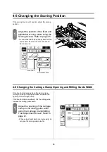
Page 64: ...ning and Milling Guide Width If the book block escapes when the machine is per forming a milling or nipping operation decrease the opening of the carriage clamp If the book block moves when it hits th...

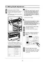
Page 65: ...djust the milling depth to 1 5mm 0 06 or 1mm 0 04 Press the Carriage Clamp Move button on the Single Operation Screen Press the Start buttons twice with both hands Press the start button once and the...

Page 66: ...tect the booklet correctly Insert each shim completely The level plate and book block are raised by the increased shim thickness and the milling depth decreases by the same amount The less the milling...

Page 67: ...grees Celsius 350 Fahrenheit Use the temperature scale shown above just for reference The glue tem perature changes depending on the room temperature Use a thermometer in the melt tank to make an accu...

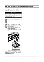
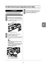
Page 68: ...ockwise Insert an Allen wrench into the hole on the plate and rotate the plate The side gluing roller on the far side will move out After adjustment tighten the locking screw If there is still not eno...

Page 69: ...unt on the application roller Move the plate to the left to increase the glue amount See the inside of the application roller shown in the illustration below to adjust the glue amount Lock the mountin...

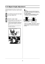
Page 70: ...rn it clock wise increase the number to lower the nip per The height changes by 0 2 mm 0 01 for each step on the scale If the spine is round turn the ring coun terclockwise If the spine is too sharp t...

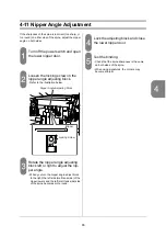
Page 71: ...below Rotate the nipper angle adjusting block left or right to adjust the nip per angle When you turn the nipper angle adjust block to the right the left side melt tank side of the nipper lowers and...

Page 72: ...er door Loosen the locking nut on the angle adjusting lever Loosen the locking knob Loosen the locking knob on the registration stopper angle adjusting lever Adjust the angle of the cover sheet Turn t...

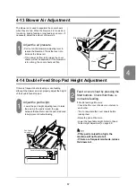
Page 73: ...hough the blower air is set properly adjust the height of the double feed stop pad Adjust the pad height Lower the pad height adjusting lever to raise the pad As the pad is raised the gap between the...

Page 74: ...e frequent mis feeds raise the feed table 4 16 Scoring Roller Pressure Adjustment If a cover sheet is cut by the scoring roller or no scor ing line is produced adjust the scoring roller pressure Open...

Page 75: ...clamp rail raises Then the carriage clamp will move to the right and stop by second press Press the Emergency Stop button and clean the level plate mecha nism If there are paper chip remove them using...

Page 76: ...r Remove any glue Apply a little silicon spray to the nipper so that the glue will not stick to the nipper Press the button Nipper Cleaning again The nipper will return the previous position Clean the...

Page 77: ...per Compressed Air Cover Sheet Detect Sensor on Feed Table Double Feed Detect Sensor 1m 1m 1m 1m Cotton Swab Brush Air Horizon Air Duster Cleaning Tool Symbol Choose the tool according to where you ar...

Page 78: ...weeks Once every 6 months The number in front of the letter indicates the multiple number Example One day 4 hours use Frequency Symbol Lubricate using a lubrication brush Lubricate using an oil appli...

Page 79: ...the carriage clamp as far as possible Select the Binding Screen to do the changeover Press the Emergency Stop button Remove the side cover Remove the two monting screws shown in the illustration belo...

Page 80: ...74 5 4 Book Support Plate Replacement Attach the new book support plate Attach the side cover Turn the Emergency Stop button clockwise to release...

Page 81: ...ss of 20 mm 0 8 on the Book Block Size Screen and perform the changeover The mounting screws on the milling guide will be removed in a later step Press the button Brake Release on the Milling Brake Re...

Page 82: ...ove the rear milling guide and the upper knife Remove the front milling guide Turn the pulley shown in the illustration below and slide out the front milling guide Remove the milling cutter Attach the...

Page 83: ...between the upper knife and the milling cutter using the thickness gauge This is the thick ness of one 64 gsm sheet Rotate the milling cutter counterclockwise slowly to check that the milling cutter...

Page 84: ...en and perform the changeover The roughening cutters will be removed in a later step Press the button Brake Release on the Milling Brake Release Screen Open the left safety cover Slide the milling sec...

Page 85: ...the power switch 8 Repeat steps 1 to 7 and remove the other roughening cutter Mount the new roughening cutters when the power is turned OFF 1 Mount each new roughening cutter so that the top of the c...

Page 86: ...eft safety cover keep pressing the brake release button on the machine and rotate the milling cutter slowly counterclock wise If the roughening cutter hits the upper knife reposition the upper knife r...

Page 87: ...on the Single Operation Screen Part 2 to lower the melt tank Turn off the power switch and open the lower nipper lower Hook the drain guide on the attach ing screws on the melt tank The attaching scr...

Page 88: ...l amount of old glue left over will mix with the new glue Do not pick the glue in fine part of the tank Picked glue may be left inside the tank and may not melt It stucks between the roller and the wi...

Page 89: ...68 and 71 Turn off the power switch Remove the two mounting screws on the double feed stop pads Now the pads can be removed Attach new pads Check that the mounting screws fit completely into the reces...

Page 90: ...pen the safety cover right Cut the transport belt using a scis sors Cut the tyton which fixes the spare transport belt shown in the illustra tion below Move the spare transport belt to the former posi...

Page 91: ...e is being applied The spine glue is turned OFF Turn the spine glue ON Page 16 The setting for spine glue is too low Increase the spine glue amount Page 22 The wiper opening is too narrow Increase the...

Page 92: ...ine of the booklet is too sharp The nipper height is too high Lower the nipper height Page 64 The nipping time is too long Make the nipping time shorter Page 24 The nipping mode with milling is select...

Page 93: ...istration stopper position is not correct Adjust the position of the registration stopper Page 26 Upper cover guide hits the regis tration stopper Make some space between the upper cover guide and reg...

Page 94: ...meet each other Align the upper and lower scoring rollers properly Page 41 The scoring line moves The transport roller is stained Wipe the transport roller using a dry cloth Page 6 The positioning gu...

Page 95: ...epth Page 59 The production speed is too fast Slow the production speed Page 10 Excess glue sticks to the delivery mechanism Too much spine glue is applied Decrease the spine glue amount Page 22 There...

Page 96: ...ount home positioning error Check that the stepper motor moves and that the home posi tioning sensor is active Service call 1111 Carriage clamp home positioning error Check that the carriage clamp mov...

Page 97: ...r Check that the breaker corre sponding to the error code is not tripped If the breaker trips repeatedly please call your local dealer Page 94 Check the rail up down position sensor B44 If this error...

Page 98: ...y please call your local dealer Page 94 Check the nipper stop position sensor B31 and nipper upper position detect sensor B32 If this error appears repeatedly replace the inverter A30 Service Call 150...

Page 99: ...ealer Page 94 Check the delivery motor stop position sensor B70 and the motor rotation Service Call Check that the delivery section is not full of bound books Page 48 1801 Thermo Fuse error Check that...

Page 100: ...ror No Location Code No Trouble 1121 1122 1123 1 Q50 Clamp Level Plate Open Close Motor M50 has trouble 1131 1132 2 Q40 Clamper Rail Up Down Motor M41 has trouble 1411 1412 3 Q30 Nipper Motor M31 has...

Page 101: ...ual Move Screen When the clamp stops above the milling section by the emergency stop this screen appears Open the safety cover and move the clamp by hand to the original position above the level plate...

Page 102: ...96...

Page 103: ...melt tank will be heated according to the weekly timer setting Turn on the power switch for main body of BQ 270 before performing the the binding operation Turn off only the power switch for main body...

Page 104: ...ps These lamps are used to indicate the current day A lighted lamp indicates the current day Day Select Switch For each day on which the melt tank will be heated automatically set the switch for that...

Page 105: ...heat up the melt tank by shifting the appropriate index tabs to the cen ter of the dial For example when the time switch is set as shown in the figure at right the machine will operate according to th...

Page 106: ...on setup time of the first day when the day select switch is set to AUTO The machine is powered off at the off setup time of the first day when the day select switch is set to OFF 1 Set the normal con...

Page 107: ...leveling bolts shown in the illustration below There are four leveling bolts Place three of them first to level the machine Adjust the leveling bolts and lift up the machine so that the machine become...

Page 108: ...and the adapter on the right side of the machine and fix with the screw Attach the trimmings bag Attach the trimmings bag on the adapter and tie it with the string Install the touch panel Remove the t...

Page 109: ...cutter may be seen rotating backward by sudden braking It is useful if you tape a string of paper on the sheet guide and touch the other side of the paper to the knife edge Press on the screen and th...

Page 110: ...hose on the machine Attach the flange where you want to connect the hose 1 Attach the hose on the flange 2 Attach the hose ufsing the hose band on the extractor Remove the cover at the electrical box...

Page 111: ...ec tion shown in the illustration above If the fan rotates backward switch the position of two wires out of three Prepare the delivery hose and install it on the delivery vent using the hose band Deli...

Page 112: ...on of Weekly Timer Option Accessory for the Weekly Timer T 270 Kit Power Switch for main body of BQ 270 Weekly Timwer and Relay 99 100 RED WHT BLK RED WHT BLK Not used for BQ 270 95 98 WHT WHT WHT BLK...

Page 113: ...screw and the fixing plate from the weekly timer 2 Insert the weekly timer to the hole 3 Fix the weekly timer using the lock screw and the fixing plate Install the power switch black for the main body...

Page 114: ...e wire No 98 from the relay to the terminal No 4 and No 9 Connect the wire No 61 from the weekly timer to the white relay con nector which wire No 21 No 22 and No 23 are connected Arrange the wires an...

Page 115: ...n Speed Without Milling Max 500 cycles hr With Milling Max 500 cycles hr Padding Max 500 cycles hr Voltage Frequency AC220V 230V 240V 50Hz 60Hz 400V 50Hz 3 phases 3 wires plus PE Rated Current AC220V...

Page 116: ...resistant Oil A930179 1 pc Single Open End Wrench M127498 1 pc Double Open End Wrench 4010556 1 pc Support Plate A931959 00 1 pc 1 0mm 0 04 M011601 1 5mm 0 06 M049499 2 0mm 0 08 M011602 1 0 mm thim i...

Page 117: ...ver 4017233 1 pc Manual Wheel A931965 1 pc Foot M005374 4 pcs Delivery Chute M126208 1 pc Trimmings Bag M005285 1 pc Spacer M127359 00 1 pc Adapter M127356 01 1 pc Use this chute when binding very sma...

Page 118: ...ok Block Insertion Guide 1 pc Drain Guide M126530 1 pc Grease Gun 4004391 1 pc Alignment Plate M027079 1 pc Thermometer 4017505 1 pc 10 80 70 100 90 Spare battery SR1130 100 80 60 120 140 160 180 200...

Page 119: ...M 220 1 box Milling Cutter M011440 1 pc Trimmings Bag M005285 2 pcs Roughening Cutter M051609 1 pc Double Feed Stop Pad A924697 1 pc Grease 4017229 1 pc Heat resistant Oil A930179 1 pc Book Support Pl...

Page 120: ...114 9 4 Option Extractor VS 270 1 pc Weekly Timer 1 pc...

Page 121: ...ver Sheet Fine Adjust Screen Part 3 27 Cover Sheet Fine Adjust Screen Part 4 28 Cover Sheet Fine Adjust Screen Part 5 28 Cover Sheet Length Seting 13 Cover Sheet Size Screen 13 Cover Sheet Width Setti...

Page 122: ...Stopper Angle Adjustment 66 Roughening Cutter Replacement 78 S Safety Function Check 35 Scoring Fine Adjust Screen 25 Scoring Position Change 58 Scoring Roller Pressure Adjustment 68 Scoring Roller Se...

Reviews: