background image

17

HARMONY and Symphony Plus  •  RIDE Technology 

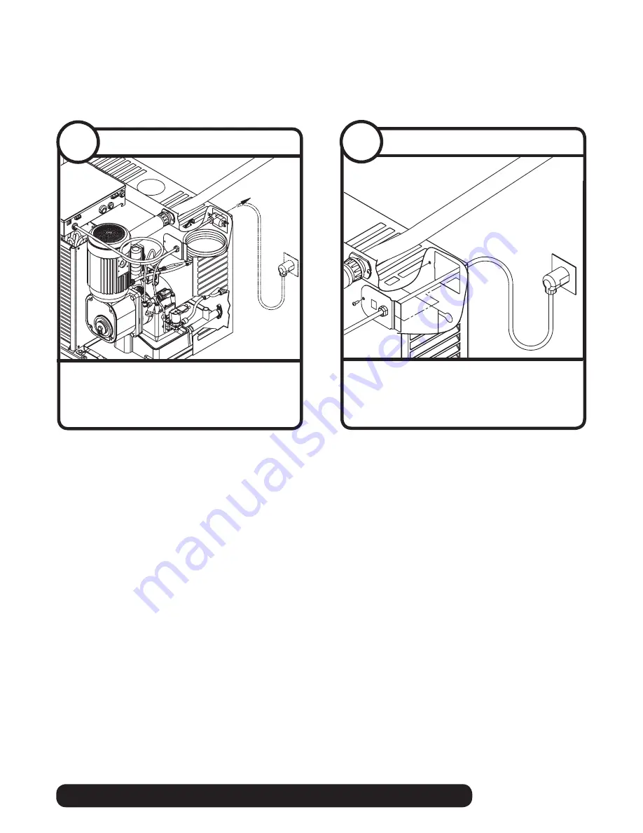
self-contained

  •  Position plate into opening and secure 

with supplied screw

Power cord

7.10

  •  Remove twist tie
  •  Carefully pass plug thru opening and plug 

into wall outlet

Power cord

7.9

Summary of Contents for HCC

Page 1: ...OM PRES SOR THER MALL Y PROT ECTE D Easto n Penn sylva nia U FULL LOAD AMPS MAX BRANCH CIRCUIT FUSE SIZE MIN BRANCH CIRCUIT AMPAC ITY DESIG N PRES SURE HIGH SIDE AMPS AMPS VOLT S CORP ORAT ION SERIA L NO NSF PHAS E SING LE CHAR GE LOW SIDE PART NO PSIG THE USA MADE IN OZ L L U R C R HZ HCC HMC HCE HME1000AHS HCC HMC HCE HME1400AHS HCC HMC HCE HME1000WHS HCC HMC HCE HME1400WHS See model number conf...

Page 2: ...0 1 icemaking head Self contained only D 115 60 1 icemaking head Self contained and remote If remote unit high side is 208 230 60 1 E 230 50 1 icemaking head Self contained only F 115 60 1 icemaking head Remote only High side is 208 230 60 3 MC Maestro Chewblet 400 Series HC Horizon Chewblet 1000 1400 1650 Series HM Horizon Micro Chewblet HC 1400 C S V A A Air cooled self contained W Water cooled ...

Page 3: ...echnology self contained Read and complete the following 8 installation steps 8 7 5 6 4 3 2 1 Front cover Internal connection External connection Louvered docking assembly Dispenser preparation Site preparation Unpack Ice transport tube ...

Page 4: ...4 self contained HARMONY and Symphony Plus RIDE Technology 1 1 2 1 2 1 1 Carefully unpack and inspect the contents of your Follett ice machine Unpack Unpack ice machine ...

Page 5: ...t be provided by end user must conform to standard EN 60 335 2 24 of the end destination Potable water supply 10 70 psi 69 483kpa 45 to 90 F 7 to 32 C Follett recommends the use of an in line water filtration system 00130286 Condenser water supply for water cooled systems 10 psi min 150 psi max 69kpa min 1034kpa max 45 to 90 F 7 to 32 C 1 5 gallons per minute 5 68 liters per minute Drain The drain...

Page 6: ...nser top 10 00 9 00 3 0 Locate hole position 9 254 mm from back and 9 229 mm from right of dispenser top Back of Top Front of Top Lancer Sensation and Touchpoint Hole location Harmony Lancer Cornelius or Servend or 110CM Symphony Plus 3 1 Remove protective tape from gaskets Top preparation 3 2 Attention The location of the hole in the dispenser top is dependent on the type of dispenser Be sure to ...

Page 7: ...i o n 1 0 m i n u t e s 2 0 m i n u t e s 3 0 m i n u t e s 4 0 m i n u t e s 5 0 m i n u t e s 6 0 m i n u t e s 7 0 m i n u t e s 8 0 m i n u t e s 9 0 m i n u t e s 1 0 0 m i n u t e s 1 1 0 m i n u t e s 1 2 0 m i n u t e s 1 3 0 m i n u t e s 1 4 0 m i n u t e s 1 5 0 m i n u t e s Switch Number O OFF X ON Agitation Frequency Agitation Time 1 s e c o n d 2 s e c o n d s 3 s e c o n d s 4 s e ...

Page 8: ...Setup FS 16 Setup FS 16 Setup FS 16 Setup FS 16 Setup Soda Plain Water OFF Time MIN 00150 On Time MSEC 01000 1000 500 34 0 104 0 104 On On On On V 1 B 1 Sold Out 1 Off Sold Out 1 Ver 0 200 Lancer FS 16 Sub Catagory Main Menu Initialization Screen 2nd Sub Catagory Boot Up Only Cancel Enter Scrolls through Main Menu Press Enter to enter sub catagory Moves curser to right or left Changes value number...

Page 9: ...hute on dual agitator Cornelius dispensers P N 307277 Diverter plate single agitator Cornelius dispensers and left hand dispense chute on dual agitator Cornelius dispensers Single Agitator Dual Agitator P N 00996207 Diverter plate right hand dispense chute on dual agitator dispensers Dispenser diverter plate overview Installation on next page 3 9 ...

Page 10: ...ifications ICE CHUTE GATE MOUNTING PLATE GASKET STORAGE HOPPER ICE DIVERTER 10 32 WASHER 10 32 NUT FLANGE EXTENDS INTO STORAGE HOPPER THROUGH GATE OPENING APPLY RTV TO THIS SURFACE TO SEAL TO HOPPER GATE MOUNTING PLATE ICE CHUTE COVER Cornelius ED DF and DB series only These dispensers require the installation of an ice diverter at the dispenser opening Disassemble chute assembly Discard factory r...

Page 11: ... provide a tight seal and prevent recirculation of hot exhaust air Left edge of cutout should be 1 75 45 mm from the left side of the ice machine Bottom edge of cutout should be 1 875 48 mm from the bottom of the ice machine Position supplied exhaust grille at least 18 458 mm away from intake grille Where possible install exhaust grille to the rear or side of the base cabinet If not using supplied...

Page 12: ... x16 cutout 305x407mm 1400 series 16 x16 cutout 407x407mm side of ice machine bottom of ice machine 1 75 45mm Access panel door on counter Top View 3D Counter View Front View CROSSBRACE Undercounter installation detail for 1000 1400 series CAUTION Keep ventilation openings in the appliance enclosure clear of obstruction To ensure proper ventilation if not using supplied grille carefully review air...

Page 13: ...sport tube to bin Be sure tube ends are square Heat end of transport tube in cup of 160 F 71 C hot water to soften and spread with pliers before making connection to ease assembly Push ice transport tube onto ice machine nipple Install hose clamp Ice transport tube to ice machine Be sure tube ends are square Heat end of transport tube in cup of 160 F 71 C hot water to soften and spread with pliers...

Page 14: ...achine must have at least 1 4 per foot pitch 6 4mm 0 3m Install ice machine potable water supply Replace access panel Air cooled ice machines only Remove access panel if necessary Install drain line The rigid drain line from the ice machine must have at least 1 4 per foot pitch Connect cooling water supply and return Install ice machine potable water supply Replace access panel Water cooled ice ma...

Page 15: ...the way into coupling and tighten nut firmly Ice transport tube 7 1 Insert potable water line into valve Push drain line over hose barb on back of evaporator mount Potable water line 7 2 Position plate into opening and secure with supplied screw Power cord 7 4 Remove twist tie Carefully pass plug thru opening and plug into wall outlet Power cord 7 3 CAUTION Plug must be accessible after final inst...

Page 16: ...ooling lines 7 5 Slide ice machine into louvered docking assembly Insert ice transport tube into coupling and tighten nut firmly Ice transport tube 7 6 Valve is preset at factory Do not adjust Adjustment will void warranty and may damage equipment ATTENTION INSTALLER Connect cooling water lines to ice machine Water valve is set at the factory DO NOT remove seal or adjust water valve Cooling lines ...

Page 17: ...nd Symphony Plus RIDE Technology self contained Position plate into opening and secure with supplied screw Power cord 7 10 Remove twist tie Carefully pass plug thru opening and plug into wall outlet Power cord 7 9 ...

Page 18: ...e MUST be sanitized prior to operation Consult Operation and Service Manual provided with ice machine for sanitizing instructions CAUTION Keep ventilation openings in the appliance enclosure clear of obstruction To ensure proper ventilation if not using supplied grille carefully review air circulation specifications in section 4 1 Remove and discard plastic grille Apply supplied gasket material ar...

Page 19: ...ology self contained max 2 ft 0 6m 1 0 3m 1 4 6 4mm Pitch ice transport tube to allow melt water to drain towards ice machine Secure insulated ice transport tube at least every 2 ft 0 6m to prevent dips or traps Long tube run recommendations ...

Page 20: ...ll free 877 612 5086 1 610 252 7301 www follettice com Horizon Maestro Harmony Ice Manager SafeCLEAN Sani Sponge and Vision are trademarks of Follett Corporation Chewblet RIDE and Follett are registered trademarks of Follett Corporation registered in the US ...

Reviews: