background image

35

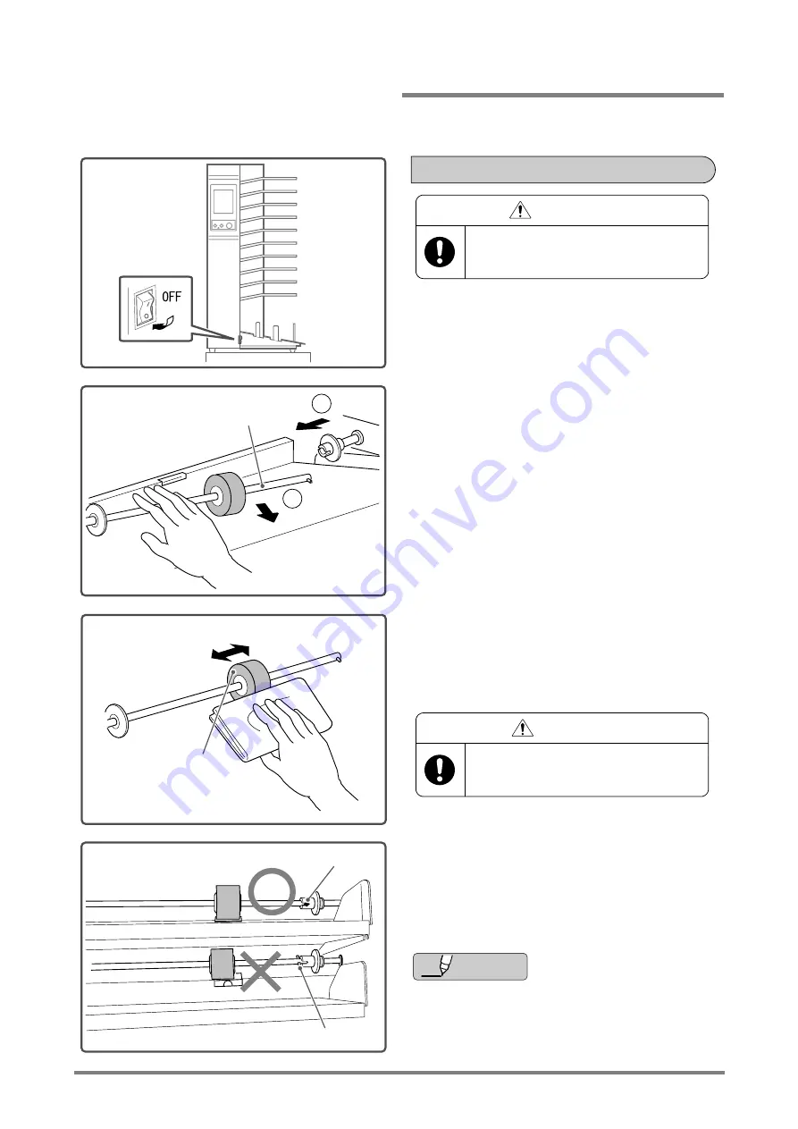
Misfeeding or jamming may occur if one of the feed rollers are stained. This can prevent the sheets from being transported smoothly.
Frequency: Once every 3 months

Turn off the power switch

• Turn off the main power switch for the QC-S300 and 

unplug the power cord.

Remove the roller shaft.

• Pull the shaft and feed roller toward the near side of 

the machine. 

• Pull out the right end of the shaft.

Clean the feed roller. 

• Clean the surface of the roller using a cloth with rub-

ber cleaner (XPF-111).

Install the roller shaft.

• When re-assembling, insert the projection on the 

roller shaft into the U-shaped cutout on the fixed 
end of the shaft.

• If double feeding or jamming occurs often even if 

the feed roller has been cleaned, the roller may 
be worn. Replace the roller with a new one.

2109640201A1

Cleaning a Feed Roller


WARNING

Turn off the main power switch and unplug
the power cord whenever a feed roller is
cleaned or replaced.

Roller Shaft

1

2

2109640201B1

2109640201C1

Feed Roller


CAUTION

When using rubber cleaner, wear rubber
gloves or clean your hands after the
cleaning operation.

2109640201D1

U-shaped Cutout

Projection

Additional 

Information

Maintenance: Feed Rollers

Summary of Contents for QC-S300

Page 1: ...er unauthorized modification or misuse or operation outside of the environmental specifications for the product Horizon International Inc pursues a policy of continuing improvement in design and performance of the product Therefore the product design and specifications are subject to change without prior notice and without our legal obligation All rights are reserved No part of this manual may be ...

Page 2: ... indicated in this manual as follows The term WARNING indicates a potentially hazardous situation which if not avoided could result in death or serious injury The term CAUTION indicates a potentially hazardous situation which if not avoided may result in serious injury or damage to the machine This symbol indicates a note which includes important information Follow the note to operate the machine ...

Page 3: ...n unstable floor surface This may allow the QC S300 to fall over and this can cause severe personal injury This can also affect the performance of the machine Warnings for Operation Maintenance Work alone when you do any operation Turn off the main power switch and unplug the power cord whenever you are cleaning the feed rollers or friction pads Do not operate the machine with any of the covers re...

Page 4: ...IV This page intentionally left blank ...

Page 5: ...ple Collated Sheets Using the Stapler 24 Trouble shooting Error Icon Appears 27 Trouble 32 Maintenance 35 Appendix Specifications 43 Collator Description 44 Control Panel Description 45 Accessories and Consumable Parts 48 CT S30 Delivery Unit for Side Stapling 50 Installation Instructions For Service How to Install a Single QC S300 Collator 53 How to Install Multiple QC S300F Collators 55 How to I...

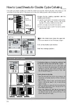
Page 6: ... Load Sheets Set Receiving Tray Enter Settings on Control Panel Press Once Press Again 1 2 3 4 5 6 7 Page 9 Page 5 Page 7 Page 9 Page 9 Page 9 Test Collating 1 set Machine remembers sheet size thickness and number of bins used The bins lift Start Collating Stop Collating Initial Screen B a c k 1 3 5 6 7 4 2 F r o n t F r o n t Offset Receiving Straight Receiving Quick Guide ...

Page 7: ... receiving tray Select the finisher or stacker 5 Collating Counter The number of collated sets appears here 6 Tab Insertion Turn this on to insert tab sheets between the collated sets Front Front Front Conveyors B a c k Trimmer SPF9 9A or MF 1 Optional Table Refer to page 45 for the control panel description Surface Front Function Settings Initial Screen If several collators are used If the SPF9 9...

Page 8: ...3 This page intentionally left blank ...

Page 9: ...etup How to Load the Sheets in the Bins 5 How to Set the Receiving Tray 7 How to Start or Stop Collating 9 Start Collating This section explains how to prepare the collator and perform basic operation procedures ...

Page 10: ...the stack of sheets Do not leave any gap between the front guide and the stack of sheets Set the support rollers Set the left support roller about 10 mm 0 39 inside the near edge of the stack Center the middle support roller between the left sup port roller and the feed roller Set the right support roller near the right edge of the sheet Wet ink can stain the collator and also cause feed prob lems...

Page 11: ...he bottom bin and the rest of the sheets above that in order When using the collator with SPF 9 9A or MF 1 The collated sets are delivered to the left 1 Load the sheets in the bins face up 2 Load the first sheets in the top bin and the rest of the sheets below that in order A3 11 x 17 A5 5 5 x 8 5 A4 8 5 x 11 8 5 x 14 A4 8 5 x 11 Feed From Short Edge Feed From Long Edge Support Stopper 2109620101E...

Page 12: ... then position the backstop so that it just touches the sheet Place the support guide 50 mm 1 97 away from the near edge of the sheet In the offset receiving mode each collated set is offset as it is stacked in the receiving tray When the main power is turned on offset receiving is selected by default See How to Load and Stack Non Standard Size Sheets on page 21 when collating A4 8 5 X 11 sheets w...

Page 13: ...that they just touch the stack Tab sheets or colored sheets can be used to separate the collated sets Load the tab sheets in either the top or bottom bin When the main power is turned on offset receiving is selected automatically To change the receiving mode press the Receiving Mode Select icon on the panel See How to Load and Stack Non Standard Size Sheets on page 21 when collating A4 8 5 X 11 sh...

Page 14: ...r to page 15 Double Cycle Function Refer to page 23 Finisher Stacker Select Refer to page 24 Press the Check button once The bins rise to the feed positions Press the Check button again One set of sheets will be collated on the receiving tray During this check the machine saves the sheet length sheet thickness and the number of bins used ON Initial Screen 2109620301A1 2109620301B1 Initial Screen F...

Page 15: ...efer to page 11 for instructions on entering the number of sets to be collated If the sheets in any bin run out the collating operation stops and the Error screen appears on the LCD display 1 Load more sheets in the indicated bin and press the Start button to lift the bins to the feeding position 2 Press the Start button again to start collating When the current job is complete if you change to a ...

Page 16: ...ypad screen appears Enter the number of sets to be collated 2 Enter the number of sets to be collated Example If you want to collate three sets press the 3 button 3 Press Ent Enter to save the setting Press the Check button The bins rise to the feeding position 2109620301B1 Initial Screen Finisher Stacker Select Double Cycle Receiving Mode Double Feed Detect Tab Insertion Collating a Preset Number...

Page 17: ... correct press the Check button to collate another set then confirm the number of sheets and the page order of the collated set If an error icon appears see Error Icon Appears Refer to page 27 through 31 Press the Start button The collating operation starts The display shows the number of collated sets After collating the preset number of sets the operation stops Take out the collated sets Pull th...

Page 18: ...13 This page intentionally left blank ...

Page 19: ...and Stack Folded Sheet 19 How to Load and Stack Non Standard Size Sheets 21 How to Load Sheets for Double Cycle Collating 23 How to Staple Collated Sheets 24 Advanced Setup This section explains how to collate sheets using the preset function and how to set up for different types of sheets ...

Page 20: ...s the Initial screen Press the upper tab on the display screen The screen on the LCD display changes Turn on the tab insertion function Now you can use the tab insertion function Press the numeric key icon Press the upper numeric key icon Using the Numeric Keypad screen enter the number of collated sets between the tab sheets Example Enter 5 using the Numeric Keypad screen The machine will insert ...

Page 21: ...umber stored for this function is cleared Press the Check button twice Press the Check button twice and check the collated set Now the machine has collated one set out of five Press the Start button The collating operation starts 2109630101E1 0 0 5 0 5 Press Important 2109630101F1 1 0 5 0 Press twice 2109630101G1 1 0 5 0 ...

Page 22: ... use the tab insertion function Press the upper numeric key icon Press the upper numeric key icon Using the Numeric Keypad screen enter the number of collated sets between the tab sheets Example Enter 5 using the Numeric Keypad screen The machine will insert tab sheets after each group of five collated sets Press Ent Enter The preset count appears on the Initial screen If the main power is turned ...

Page 23: ... one set out of five Press the Start button The collating operation starts In this example collating stops when the machine has completed 10 blocks 50 sets To continue the collating operation To continue the collating operation for the same number of sets 1 Press the Start button to start collating again It is not necessary to enter the numbers again To change the preset numbers and continue colla...

Page 24: ...eiving tray 2 Position the support stopper to support the back of the stack as shown Straight Receiving 1 First position the backstop and the front guides against the edges of the sheet as it sits on the receiving tray 2 Position the support stopper to support the back of the stack as shown Folded Sheet Size 8 5 x 11 long edge feed Offset Receiving 1 Set the front guides to the 11 positions 2 Posi...

Page 25: ...ceiving mode straight or offset on the Ini tial screen Start the collating operation Use the preset function when collating folded sheets The folded edges will take up more space in the receiving tray and the collated sheets may fall over before triggering a receiving tray full error Refer to page 11 2109630301E1 Front Guides Front Guides Stacking Area Width x Length 180 x 175 mm 7 1 x 6 9 or more...

Page 26: ...eiving tray 2 Position the support stopper to support the back of the stack as shown When feeding 8 5 X 11 size sheets from the long edge Load the sheets into the bins Load the sheets into the bins in the position shown in the illustration to the left Set the receiving tray Offset Receiving 1 Set the front guides to the 11 positions 2 Position the support stopper to support the back of the stack a...

Page 27: ...sits on the receiving tray 2 If the backstop and front guides do not support the stack use the support stopper Set the receiving mode Select the receiving mode straight or offset on the Ini tial screen Start the collating operation If the sheets are not stacked correctly because of static electricity reset the backstop 10 to 20 mm 0 4 to 0 8 away from the edge of the stack 2109630401C1 Bin Support...

Page 28: ...m section A run out other sheets will be fed from section B automatically This means that collating can continue One collator 5 bins each sec tion Two collators 10 bins each section Three colla tors 15 bins each section Loading Sheets into the Bins Place the tab sheets in the top bin one collator or the top and the next highest bins two or three collators in each section When a single collator is ...

Page 29: ... collator only Select the finisher on the Initial screen Set up the finisher Set up the finisher Refer to the operation manual for your finisher Start the collating operation F r o n t F r o n t F r o n t F r o n t F r o n t F r o n t 2109630601A1 Top 1st 2nd 3rd 2109630601B1 Initial Screen Finisher Stacker Select Control 10st 9st 8st 7st 6st 5st 4st 3st 2st 1st 20th 2nd 1st 10st 19st 18st 17st 16...

Page 30: ...25 This page intentionally left blank ...

Page 31: ...f Sheets 32 Operating Problems 33 Problems with CT S30 Delivery Unit for Side Stapling 34 Maintenance Feed Rollers 35 Friction Pads 37 Double Feed Detect Sensor 38 Transport Rollers and Transport Belt 39 Receiving Tray Full Detect Sensor 40 CT S30 Delivery Unit for Side Stapling 41 Troubleshooting This section explains how to correct some simple problems and how to maintain the collator ...
Page 32: ...em Page 5 Check whether the fric tion pad is stained with ink Clean the friction pad Page 37 Check the setting of the feed pressure adjusting block under each bin If a block is set to the strong position reset it to the normal position Check the setting of the pad pressure adjusting lever on the left side of the collator Open the transport door and check the setting of the pad pressure adjusting l...

Page 33: ... strong position Check the setting of the pad pressure adjusting lever on the left side of the collator Open the transport door and check the set ting of the pad pressure adjusting lever If the lever is set to the strong lower position reset it to the normal upper position Check whether the sheets being used are within the specifications for type and size Use sheets which are within the specifica ...

Page 34: ...tely or let the sheets sit for a while Page 5 Check whether the sheets are held together by ink When using thick sheets set the feed pres sure adjusting block on each side to the strong position Check whether the transport rollers or transport belts are stained Clean the transport rollers or the transport belts Page 39 Check whether the double feed detect sen sor is covered with paper dust Clean t...

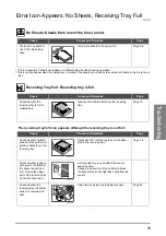
Page 35: ...ed sets Remove the collated sets from the receiving tray Page 10 Check Causes and Remedies Page Check whether collated sheet is stuck on the rear guide or backstop in the receiving tray Reposition the front rear guide and the back stop in the receiving tray Page 7 8 Check whether a strong light source is affecting the sensor beam func tion Check the upper part of the receiving tray on the front an...

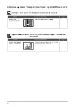
Page 36: ...door completely Check Causes and Remedies Page Check whether there are problems on the finisher Correct the cause of the problem Refer to the operation manual for the finisher 2109640103G1 Optional Module Error There is a problem with the stapler connected to the collator 2109640105A1 Option Error Icon Appears Transport Door Open Optional Module Error ...

Page 37: ...whether the front guide is set against the edge of the stack too tightly or too loosely If the front guide is set too tight set the guide so that it just touches the edge of the stack If the front guide is set too loose posi tion the front guide up against the stack without any gap Page 5 Check whether the sheets are held together by static electricity Reset the backstop 10 to 20 mm 0 4 to 0 8 awa...

Page 38: ...turn off the preset function Page 17 Check Causes and Remedies Page The sheets jam inside the middle conveyor Hold the lever and open up the conveyor using both hands then remove the jammed sheets The sheets jam inside the upper conveyor Open up the conveyor using both hands then remove the jammed sheets 2109640106D1 OFF 2109640107A1 2109640107B1 WARNING Hold the conveyor tightly so that your hand...

Page 39: ... your local dealer Service Call The gap between the upper delivery guide and the lower delivery guide is not set to 5 mm 0 2 Call your local dealer Service Call Check whether the deliv ery guide is dirty Clean the delivery guide Check Causes and Remedies Page The power cord of the CT S30 is not connected to the collator Connect the power cord of the CT S30 to the collator 2109640108A1 2109640108B1...

Page 40: ...XPF 111 Install the roller shaft When re assembling insert the projection on the roller shaft into the U shaped cutout on the fixed end of the shaft If double feeding or jamming occurs often even if the feed roller has been cleaned the roller may be worn Replace the roller with a new one 2109640201A1 Cleaning a Feed Roller WARNING Turn off the main power switch and unplug the power cord whenever a...

Page 41: ... Lock the feed roller against the flange of the wheel If the feed roller is installed in the wrong direction misfeeding may occur Install the roller shaft When re assembling insert the projection on the roller shaft to the U shaped cutout on the fixed end of the shaft 2109640201A1 Replacing a Feed Roller WARNING Turn off the main power switch and unplug the power cord whenever the feed roller is c...

Page 42: ...ming occurs often even if the friction pad has been cleaned the pad may be worn Replace the pad with a new one Install the friction pad and the roller shaft When re assembling insert the projection on the roller shaft into the U shaped cutout on the fixed end of the shaft 2109640201A1 Cleaning and Replacing a Friction Pad WARNING Turn off the main power switch and unplug the power cord whenever a ...

Page 43: ...power switch Turn off the main power switch on the QC S300 and unplug the power cord Clean the double feed detect sensor Clean the double feed detect sensor using the accessory brush 2109640201A1 Cleaning the Double Feed Detect Sensor WARNING Turn off the main power switch and unplug the power cord whenever the double feed detect sensor is cleaned or replaced Double Feed Detect Sensor Feed Section...

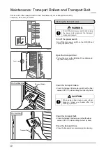
Page 44: ...turning the rollers by hand Clean the transport belt Clean the transport belt using a cloth with rubber cleaner XPF 111 while turning the belt by hand Close the transport door Close the transport door completely after cleaning 2109640201A1 Cleaning the transport roller WARNING Turn off the main power switch and unplug the power cord whenever the transport rollers are cleaned Lever 2109640204A1 210...

Page 45: ...h or compressed air The sensors work together First clean just the rear sensor The lens of the sensor is located behind the hole If the same symptom occurs again during collat ing go to the next step and also clean the sensor on the front of the machine Clean the receiving tray full detect sensor on the front of the machine Remove any paper dust on the sensor by blowing compressed air through the ...
Page 46: ...CT S30 Clean the delivery guides Clean the delivery guides with a cloth soaked in alcohol Adjust the angle of the upper delivery guide so that the distance between the upper delivery guide and lower delivery guide is about 5 mm 0 2 After making this adjustment tighten the screws for the upper delivery guide 2109640201A1 Cleaning the CT S30 WARNING If the delivery gates are dirty the collated sheet...

Page 47: ...ifications 43 Collator Description 44 Control Panel Description 45 Accessories and Consumable Parts 49 CT S30 Delivery Unit for Side Stapling 51 Appendix This chapter includes some useful informations about the QC S300 ...

Page 48: ...4 or 8 5 x 11 feeding from long edge Receiving Tray Stacking Offset Stack Straight Stack Receiving Tray Capacity 75 mm 2 95 Program Collation Double Cycle Mode Tab Sheet Insertion Mode Preset Stop Other Functions Energy Saving Mode The machine goes into this mode after a preset time Voltage Frequency QC S300 100VAC 50 Hz 60 Hz 1 5 1 6A 115VAC 60 Hz 1 4A 230VAC 50 Hz 60 Hz 0 7 0 8A QC S300F 100VAC ...

Page 49: ...for multiple Collators Connector to other Machines Circuit Breaker Power Cord Socket Pressure Strong Pressure Normal Bins 1 through 10 Pressure Normal Pressure Strong Door Open Close Lever Optional Table LCD Display Touch Panel Connector for CT S30 2109640302A1 Test collating 1 set Values for sheet size thickness and number of bins used are saved Collator Description Feeding Pressure Adjusting Blo...

Page 50: ...eset number using the Numeric Keypad screen Tab Insertion Function Select Button On The tab insertion function is active To set the number of collated sets between tab sheets Enter the number of collated sets between tab sheets using the upper Numeric Key icon To set the number of blocks of collated sets Enter the number of collated sets between tab sheets using the upper Numeric Key icon Enter th...

Page 51: ...tect Function Icon This icon shows whether or not the double feed detect function is active Receiving Mode Icon This icon shows the receiving mode straight or offset These icons show the current condition of the bins Icons appear for any bins being used These icons show the current settings for the machine Initial Screen Press Current Settings Screen 2109640303B1 Initial Screen Information Screen ...

Page 52: ...e tower which has the error is shown on the screen now Double Feeding Misfeeding Sheet Jam No Sheet Receiving Tray Full Optional Module Error Transport Door Open There are errors on any towers indicated in gray or black OK Button Press this button after correcting the cause of the error The Initial screen appears Each Error icon indicates the meaning and the position of the error 2109640303D1 Refe...

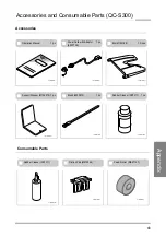
Page 53: ...4158 10 pcs 2109640304A1 2109640304B1 2109640304C1 Support Stopper M154218 1 pc Brush 4000972 1 pc Rubber Cleaner XPF 111 1 pc 2109640304D1 2109640304E1 2109640304F1 Rubber Cleaner XPF 111 Friction Pad M014225 Feed Roller M021147 2109640304G1 2109640304H1 2109640304I1 Accessories and Consumable Parts QC S300 ...

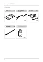
Page 54: ... Operation Manual 1 pc Power Cord with Adaptor 1 pc 4007736 Bin M154158 10 pcs 2109640304A1 2109640304B1 2109640304C1 Brush 4000972 1 pc Rubber Cleaner XPF 111 1 pc 2109640304E1 2109640304F1 Accessories for QC S300F ...

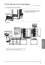
Page 55: ... Delivery Unit for Side Stapling 2109640305A1 Control panel F r o n t F r o n t F r o n t F r o n t 10th 9th 8th 7th 6th 5th 4th 3rd 2nd Top 1st 20th 2nd 1st Last 20th 19th 18th 17th 16th 15th 14th 13th 12th 11th Feed Receiving Tray On deliver to the left SPF9 9A CT S30 Delivery Unit for Side Stapling 2109640305B1 Refer to the operation manual for the SPF 9 9A CT S30 Delivery Unit for Side Staplin...

Page 56: ...51 This page intentionally left blank ...

Page 57: ... 55 Multiple Collators QC S300 QC S300F QC S300F Installation Space in mm inches 2 170 85 5 x 580 22 9 x 1 033 40 7 Optional Table MT 100 How to Install the CT S30 Delivery Unit for Side Stapling 62 Delivery Unit for Side Stapling CT S30 Installation Instructions for Service Engineer This page includes installation instructions for the machine These instructions should only be used by trained serv...

Page 58: ...feet on the QC S300 fit into the holes on the MT 100 Place the MT 100 in the correct direction referring to the illustration to the right 3 Attach the QC S300 using two screws 4 Move the machine to the required location Be sure to push the bottom of the transport door side of the QC S300 when moving the machine Do not push the bin side This could cause the QC S300 to fall over 5 Lock the casters o...

Page 59: ... the steps 1 through 3 4 Plug the power cord into the QC S300 5 Plug the power cord into an outlet Plug the power cord into a properly grounded outlet If you must use an ungrounded outlet be sure to ground the machine separately A poor ground can cause problems for the machine due to by static electricity lightning strikes or current leakage How to Install a Single QC S300 Collator 2109650101D1 Pi...

Page 60: ...wer Conveyor 1 pc 2109650201A1 2109650201B1 2109650201C1 Solenoid Connector 1 pc Support Guide l154294 1 pc Gear M092610 Clevis Pin 1 pc each 2109650201D1 2109650201E1 2109650201F1 Conveyor Support Plate 1 pc Bridge 1 pc Connecting Plate 1 pc B4 8ZP x 3 2109650201G1 B4 8ZP x 2 2109650201H1 B5 10ZP x 4 2109650201I1 ...

Page 61: ...ring to the illustration to the right 3 Mount the QC S300F using two screws 4 Temporarily place the QC S300F 1 m 40 to the left of the other QC S300F unit as shown in the illustration viewed from the front Be sure to push the bottom of the transport door side of the QC S300F when moving the machine Do not push the bin side This could cause the QC S300F to fall over How to Install Multiple QC S300F...

Page 62: ...300F 1 Remove the locking screw on the middle con veyor How to Install Multiple QC S300F Collators Preparation for Multiple QC S300F Collators 2109650202C1 Rear Cover QC S300F 2109650202D1 Gear Cover QC S300F Install the lower conveyor on the QC S300F 2109650202E1 CAUTION The tip of the stainless steel guide can bend easily Install the guide carefully 2109650202F1 Positioning Shaft Stainless Steel...

Page 63: ...he machine 2 Attach the gear using a clevis pin 3 Rotate the pulley by hand and check that the gear turns smoothly 4 Attach the gear cover using three screws Be careful that the nearby cables are not caught How to Install Multiple QC S300F Collators 2109650202H1 Drive Shaft 2109650202I1 End of shaft 2109650202J1 End of shaft Locking Screw Attach the accessory gear to the QC S300F 2109650202K1 Driv...

Page 64: ...sert the two positioning pins on the conveyor support plate into the two holes on the bottom of the conveyor When inserting the positioning pin move the QC S300 5 Attach the lower conveyor using the conveyor locking plate using two mounting screws How to Install Multiple QC S300F Collators Attach the upper conveyor to the middle conveyor 2109650202M1 Upper Conveyor Middle Conveyor U shaped Cutout ...

Page 65: ...t the ground of sup port guide next to the connector using a screw 2 Attach solenoid connector A to the right connector on the QC S300F 3 Attach solenoid connector B to the connector on the conveyor 4 Attach solenoid connector C to the left connector on the QC S300 How to Install Multiple QC S300F Collators 2109650202R1 Connecting Plate 2109650202S1 Support Guide Wiring Between the QC S300 and the...

Page 66: ...S300F 6 Plug the power cord into an outlet Plug the power cord into a properly grounded outlet If you must use an ungrounded outlet be sure to ground the machine separately A poor ground can cause problems for the machine due to by static electricity lightning strikes or current leakage How to Install Multiple QC S300F Collators 2109650101D1 Pin Arm 2109650101E1 U shaped Cutout Pin Arm 2109650101F...

Page 67: ... the SPF 9 9A stapler forward or backward so that the rear edge of the lower delivery guide aligns with the mark on the jog guide of the stapler At this point adjust the position of the SPF 9 9A by moving the whole unit Do not use the position adjustment handle on the SPF 9 9A How to Install the CT S30 Delivery Unit for Side Stapling WARNING Turn off the power switches for both the col lator and t...

Page 68: ...very guide so that the gap between the upper delivery guide and the lower delivery guide is 5 mm 0 2 Loosen the mounting screws above the upper delivery guide to adjust the angle of the guide After making the adjustment lock the position of the upper delivery guide by tightening the two screws 7 Install the covers on both sides using four screws 3 Connect the power cord for the CT S30 to the colla...

Page 69: ...lded Sheets 19 How to Load and Stack Irregular Size Sheets 21 How to Load Sheets on Bins 5 I Information Screen 46 M Maintenance 35 Misfeed 28 N No Sheets 30 Numeric Keypad Screen 45 O Offset Receiving 7 Operating Problems 33 Optional Module Error 31 P Poor Arrangement of Sheets 32 Power Switch 44 Present Setting Screen 46 Preset Tab Insertion Function 17 R Rear Guide 44 Receiving Mode Select Butt...

Page 70: ...65 This page intentionally left blank ...

Reviews: