background image

15

EN

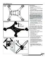
Airframe Maintenance

Replacing the body

Disassembly of the old airframe

1. Ensure the battery is disconnected from the

quadcopter. 

2. Remove the 2 machine screws from each propeller 

and remove the propellers. 

3. Remove the 32 1.5mm hex screws from the bottom 

of the frame to separate the upper and lower body 
pieces.

4. Unplug the compass sensor from the fl ight control 

board. Remove the landing gear with compass sen-
sor and place it in a safe area away from magnets. 

NOTICE:

 Do not allow the compass sensor to

get near a magnet. Any magnet, including those in 
the 350 QX2 motors, can damage the compass and 
cause it to work incorrectly. If the 350 QX2 is fl own 
with a faulty compass, all GPS functions will be 
compromised. 

5. Unplug the GPS receiver from the fl ight control 

board and remove the battery tray assembly.

6. If you are replacing the GPS components, remove 

the foil from the GPS receiver and unplug the GPS 
antenna from the GPS receiver. 

7. Remove the fl ight control board from the airframe.

8. Remove the receiver.

9. Remove the motors and ESCs from the airframe.

Before installing the components into the new airframe, 
inspect all the components for any obvious damage or 
burnt smells. Check the motors for smooth bearings 
and inspect all the propellers for chips, burrs or cracks. 
Replace any parts in question. 

Installing components in the new airframe

1. Install the motors and ESCs, making sure to match 

the wire colors on the connectors.

2. Install the receiver.

3. Install the fl ight control board.

4. Install the tray assembly.

5. Install the GPS receiver and GPS antenna and plug 

the cables into their corresponding sockets.

6. Assign the motors and ESCs according to the

ESC and Motor Assignment Procedure.

7. Install the landing gear and connect the compass 

to the fl ight control board. If you replaced the 
compass or believe that it may have been impaired 
by a magnetic fi eld, you will need to perform the 
compass calibration procedure. 

8. Mount the top of the airframe.

9. Install the propellers, paying attention to the

direction of rotation as indicated by the arrows 
molded in the frame and on the propellers for each 
motor.

Body Screw
Locations

Propeller Direction of Rotation Indicators

Internal Components

Motors
ESCs
GPS receiver
GPS antenna
Battery tray assembly
Flight control board

Rotation 
direction

Motor number

Summary of Contents for Blade 350 QX2

Page 1: ...Instruction Manual ...

Page 2: ...ted to compatibility and performance of counterfeit products or products claiming compatibility with DSM or Spektrum WARNING Read the ENTIRE instruction manual to become familiar with the features of the product before operating Failure to operate the product correctly can result in damage to the product personal property and cause serious injury This is a sophisticated hobby product It must be op...

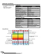
Page 3: ...product online visit www bladehelis com Box Contents 4 Charging Warnings 4 Low Voltage Cutoff LVC 4 Charging the Flight Battery 5 Transmitter Setup BNF 5 Mounting a Camera 6 Connecting the Flight Battery 7 Transmitter Control Layout RTF 7 Power On 7 Binding 8 Flight Mode Switches RTF 9 Flight Modes Explained 9 Audible Alerts and LED Codes 10 GPS Functionality of the 350 QX2 12 Flight Guidelines an...

Page 4: ...ile charging ONLY USE A CHARGER SPECIFICALLY DESIGNED TO CHARGE LI PO BATTER IES Failure to charge the battery with a compatible charger may cause a fire resulting in personal injury and or property damage Never discharge Li Po cells to below 3V under load Never cover warning labels with hook and loop strips Never leave charging batteries unattended Never charge batteries outside recommended levels...

Page 5: ...ottle trim until motors stop turning Press and HoldTRAINER BIND Release to EXIT Position 1 AP Mode Position 2 Stability Mode DX5e New w 3 position switch N A N A N A N A Position 0 SMART Mode Lower throttle trim until motors stop turning Press and HoldTRAINER BIND Release to EXIT Position 1 AP Mode Position 2 Stability Mode DX6i Acro THRO N ELEV N GEAR R AILE N RUDD N FLAP N ACT TravelAdj GEAR POS...

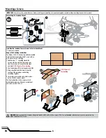
Page 6: ... A around the camera with the metallic side facing away from the camera so it covers the top sides and back DO NOT peel off the backing 2 Peel the backing off the rectangular sheet B 3 Wrap sheet B around the back of sheet A sealing all the rear edges and holding everything together 4 The shield is removable and is held in place by the 350 QX2 camera mount The front and bottom of the camera are le...

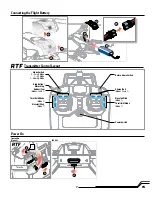
Page 7: ...art Mode 1 AP Mode 2 Stability Mode Return Home Switch Aileron Roll Modes 2 and 1 Bind Button Motor Stop Elevator Pitch Mode 2 Throttle Altitude Mode 1 Rudder Yaw Modes 2 and 1 Throttle Altitude Mode 2 Elevator Pitch Mode 1 Power Switch 4 Power On 1 2 3 Transmitter Mode 2 350 QX2 RTF Throttle ...

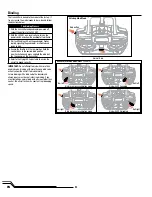
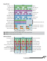
Page 8: ...ion see illustrations and press and hold the bind but ton then power on the transmitter 5 Refer to the Flying LED Codes table to ensure the aircraft is bound correctly Normal Bind Roll left Yaw left Roll right Yaw right Bind with GPS enabled Bind in compass calibration mode Bind with GPS disabled Bind in pressure calibration mode Bind button IMPORTANT Do not attempt to bind with more than one bind...

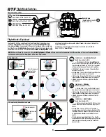
Page 9: ...tor and aileron inputs are at neutral Self Leveling Brings the 350 QX2 to a level attitude when the elevator and aileron inputs are at neutral Altitude Command Altitude is relative to throttle stick position Stick Relativity SAFE Circle Aircraft response relative to the pilot location Elevator input Aileron input Forward Right Left Back NOTICE Do not attempt to fly your 350 QX2 in Stability Mode or...

Page 10: ...on many continuous tones with increasing frequency RC signal detected after start one long tone Bind detected one long tone Bind accepted 3 seconds after detected one long tone Throttle stick in correct position for motor start low med high happy tone Cannot start motors because of low voltage high med low sad tone Cannot start motors because vehicle is tilted high med low sad tone Enter ESC ID as...

Page 11: ...sensor temperature calibration 3 purple flashes pause Rapid red and blue flashing AP Mode GPS disabled Pressure and gyro calibration Slow purple flash Rapid red green and blue flashing Stability Mode with GPS lock Accelerometer offset calibration entered in flight only Accelerometer offset calibration started in flight only Calibration failed These items are performed by the manufacturer The LED may ran...

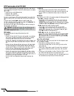
Page 12: ...en if the flight control system loses its orientation because of aggressive flight in 3 axis mode Once the 350 QX2 has landed in Return Home mode it will disarm the motors With GPS OFF If Return Home mode is activated the 350 QX2 will level off and land quickly using the barometric pressure sensor to maintain the descent rate Once the 350 QX2 has landed in Return Home mode it will disarm the motors ...

Page 13: ...change your position 1 Power on the transmitter with the flight mode set to Smart Mode and the throttle stick down 2 Install a charged battery plug it in and close the hatch 3 With the quad on a level surface turn on the power switch and allow the 350 QX2 to initialize If the GPS is enabled wait for the GPS signal to be acquired which is indicated by a solid green LED It may take from 30 90 seconds...

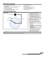
Page 14: ...may cause the 350 QX2 to fly directly over the pilot if the aircraft was flown to a position behind where the pilot was standing when the home position was established Switch to position 1 Returning the switch to position 0 will stop the Return Home program Landing To land the 350 QX2 there are two options Guide the aircraft to where you wish to land and re duce the throttle Hold the bind button for...

Page 15: ...rframe Before installing the components into the new airframe inspect all the components for any obvious damage or burnt smells Check the motors for smooth bearings and inspect all the propellers for chips burrs or cracks Replace any parts in question Installing components in the new airframe 1 Install the motors and ESCs making sure to match the wire colors on the connectors 2 Install the receive...

Page 16: ... the calibration procedure again The pressure sensor is calibrated at the factory on the 350 QX2 Recalibration should only be necessary if you replace the sensor 1 Place the 350 QX2 in a cold area Allow it to remain in the cold for 30 minutes or more 2 Bring the 350 QX2 out of the cold and into a warm area The greater the differ ence in temperature between the cold and warm areas the more accurate...

Page 17: ...me to shut off after completing return to home Pressure calibration is needed Refer to the Pressure Sensor Calibration section of this manual The quadcopter has trouble finding the home position and the props will not shut off after returning home Accelerometer calibration is needed Refer to the Accelerometer Calibration section of this manual ESC and Motor Assignment Procedure Motor Numbers 1 Begi...

Page 18: ...istered trademarks of Horizon Hobby LLC The Spektrum trademark is used with permission of Bachmann Industries Inc GOPRO is a registered trademark of Woodman Labs Inc in the United States and other countries All other trademarks service marks and logos are property of their respective owners US 7 391 320 Other patents pending Created 6 14 45967 ...

Reviews: