background image

EN

21

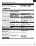
Troubleshooting Guide

Problem

Possible Cause

Solution

Trim change when flight mode is switched

Trim is not at neutral

If you need to adjust the trim more than 8 clicks, return the trim to 

neutral and manually adjust the clevis to center the trim

Sub-Trim is not at neutral

Do not use Sub-Trim. Adjust the servo arm or the clevis

AS3X

®

 System Trouble Shooting Guide

Problem

Possible Cause

Solution

Aircraft does not operate

There is no link between the transmitter and receiver

Re-Bind the system following directions in this manual

Transmitter AA batteries are depleted or installed 

incorrectly as indicated by a dim or unlit LED on the 

transmitter or the low battery alarm

Check polarity installation or replace with fresh AA batteries

No electrical connection

Push connectors together until they are secure

Flight battery is not charged

Fully charge the battery

Crash has damaged the radio inside the fuselage

Replace the fuselage or receiver

Aircraft keeps turning in one direction

Rudder or rudder trim is not adjusted correctly

Adjust stick trims, then land and manually adjust aileron and/or 

rudder linkages so no transmitter trim is required

Aileron or aileron trim is not adjusted correctly

Adjust stick trims or manually adjust aileron positions

Aircraft is difficult to control

Wing or tail is damaged

Replace damaged part

Damaged Rotor

Land immediately and replace damaged Rotor

Center of gravity is behind the recommended location

Shift battery forward, do not fly until correct Center of Gravity 

location is achieved

Aircraft nose rises steeply at half 

throttle

Wind is too gusty or strong

Postpone flying until the wind calms down

Elevator is trimmed ‘up’ too much

If trim must be adjusted more than 4 clicks when pushing the 

trim button, adjust push rod length

Battery is not installed in the correct position. 

Move forward approximately 1/2”

Aircraft will not climb

Battery is not fully charged

Fully charge battery before flying

Elevator may be trimmed ‘down’

Adjust elevator trim ‘up’ 

Rotor damaged

Land immediately, replace Rotor

Aircraft is difficult to launch in the 

wind

Launching the aircraft down wind or into a cross wind

Always launch the aircraft directly into the wind

Flight time is too short

Battery is not fully charged

Recharge battery

Flying at full throttle for the entire flight

Fly at just above half throttle to increase flying time

Wind speed too fast for safe flight

Fly on a calmer day

Rotor damaged

Replace Rotor

Aircraft vibrates

Rotor, spinner or motor damaged

Tighten or replace parts

Rudder, ailerons or elevator do not 

move freely

Damaged or blocked push rods or hinges

Repair damage or blockage

Aircraft will not Bind  

(during binding) to transmitter

Transmitter is too near aircraft during binding process

Move powered transmitter a few feet from aircraft, disconnect 

and reconnect battery to aircraft

Aircraft or transmitter is too near a large metal object, 

wireless source or another transmitter

Move the aircraft and transmitter to another location and 

attempt binding again

Flight battery/transmitter battery charge is too low

Replace/recharge batteries

Aircraft will not connect  

(after binding) to transmitter

Transmitter is too near aircraft during connecting process Move powered transmitter a few feet from aircraft, disconnect 

and reconnect battery to aircraft

Aircraft or transmitter is too near a large metal object, 

wireless source or another transmitter

Move the aircraft and transmitter to another location and 

attempt connecting again

Aircraft battery/Transmitter battery charge is too low

Replace/recharge batteries

Transmitter may have been bound to a different model 

(using different DSM Protocol)

Bind aircraft to transmitter

After being properly adjusted, aileron 

and/or rudder are not in neutral 

position when battery is plugged in

Model was moved during initial power on

Unplug flight battery and reconnect, keeping model immobile 

for at least 5 seconds

Summary of Contents for E-Flite HABU STS

Page 1: ...Instruction Manual Bedienungsanleitung Manuel d utilisation Manuale di Istruzioni SAFE Select Technology Optional Flight Envelope Protection ...

Page 2: ...s tab for this product MEANING OF SPECIAL LANGUAGE The following terms are used throughout the product literature to indicate various levels of potential harm when operating this product WARNING Procedures which if not properly followed create the probability of property damage collateral damage and serious injury OR create a high probability of superficial injury CAUTION Procedures which if not p...

Page 3: ...ng Guide 21 Optional Landing Assist Sensor LAS Upgrade 22 Service and Repairs 23 Replacement Parts 24 Recommended Parts 24 Optional Parts 24 AMA National Model Aircraft Safety Code 25 Limited Warranty 26 Warranty and Service Contact Information 26 FCC Information 27 IC Information 27 Compliance Information for the European Union 27 Box Contents Motor 2847 3200Kv 6 Pole Brushless motor SPMXAM1100 I...

Page 4: ...er load Never cover warning labels with hook and loop strips Never charge batteries outside recommended levels Never attempt to dismantle or alter the charger Never allow minors under the age of 14 to charge battery packs Never charge batteries in extremely hot or cold places recommended between 40 120 F or 5 49 C or place in direct sunlight Charger Warnings From the box to the air 1 Remove and in...

Page 5: ...3 port and insert the battery balance lead B into the charger balance port Both the IC3 and balance connectors must be connected for the charging process to begin The battery may be disconnected from the charger at any time to stop the charging process IMPORTANT SMART NiMH batteries do not have a balance connector 3 Disconnect the IC3 and balance connectors when the charge and balance cycles are c...

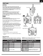
Page 6: ...aining section for setup of other Spektrum Transmitters Hi Lo Rate Switch F Switch This switch supports high and low rate functions on aileron elevator and rudder channels In the upper or HI position servo travel is 100 on these channels In the lower or LO position servo travel decreases to 70 This switch lets you quickly change control rates from high for aggressive maneuvers to low for smooth pr...

Page 7: ... Spektrumrc com and update your firmware With the latest firmware installed on your transmitter the telemetry option should now be functional on your transmitter Dual Rate High Rate Low Rate Aileron 100 70 Elevator 100 70 Rudder 100 70 The included DSMX full range transmitter features dual rates to allow you to select the amount of travel that you want from the control surfaces SMART Technology El...

Page 8: ...is negative 2 Install the nose gear assembly A into the fuselage with the air vent facing forward 3 Secure the nose gear assembly using the eight 2 x 8mm screws C Disassemble in reverse order Main Gear Installation 1 Position the aircraft so the bottom of the wing faces up 2 Insert the main gear strut A into the gear plate hole located on the wing 3 Carefully turn each strut in the gear plate unti...

Page 9: ... screws C 4 Manually position the rudder servo arm as shown D 5 Align and press the tail cone E on the rear of the fuselage and secure the cone in place with included tape F 6 Align the vertical fin with the fuselage and guide the rudder servo arm through the hole of the vertical fin base 7 Secure the vertical fin to the fuselage with three 2 5 x 8mm screws G 8 Attach the Z bend of the linkage H i...

Page 10: ...er C 4 Attach the appropriate control surfaces to the their respective ports on the flight controller using the table at the right 5 Using double sided servo tape not included the flight controller to the platform at the rear of the receiver compartment as shown The flight controller should be mounted in the orientation shown parallel to the length of the fuselage with the label facing up and the ...

Page 11: ...rt office Failsafe If the receiver loses transmitter communication the failsafe will activate When activated failsafe moves the throttle channel to its preset failsafe posi tion low throttle that was set during binding All other channels move for the aircraft to slowly circle and descend until radio link is re established Binding Procedure 1 Make sure the transmitter is powered off 2 Make sure the...

Page 12: ... initializes If the aircraft does not initialize after about 30 seconds because of too much movement disconnect and reconnect the flight battery to re initialize the system After the SAFE system initializes the rudder will move back and forth then come to neutral to indicate the SAFE system has initialized and is ready to operate If you accidentally connect the battery while the throttle is not a ...

Page 13: ...lance when suspended at that point After installing the battery in the recommended position and before powering on the ESC switch verify the CG by supporting the aircraft 90 95mm approximately 3 74 inches back from the wing root as shown 3S 4000mAh Smart battery CG position The battery is installed all the way forward in battery compartment Only the front battery strap will be used 4S 4000mAh Smar...

Page 14: ...ttery and keep the aircraft immobile for 5 seconds 2 Face the model with the transmitter in your normal flying position 3 Toggle back and forth 1 toggle the HI LO Rate switch rapidly 4 times and then press and hold the bind button The transmitter LEDs will flash and the alarm will sound The system is in range check mode Do not let go of the bind button until you are finished with the range check I...

Page 15: ...l automatically be in beginner mode when below 100 feet Experienced Mode position 2 Flight Controller LED Red Natural Flight Experience The pilot experiences natural AS3X flight for smooth handling and outstanding precision Unlimited Flight Envelope No limit on Pitch and Roll angles airframe limited Panic Recovery This function is intended to provide you with the confidence to continue to improve ...

Page 16: ... to make the aircraft go down Pull the elevator stick back to go up Aileron right and left Move the aileron stick right to make the aircraft roll or bank right Move the aileron stick left to bank left TIP Always picture yourself in the aircraft when determining which way to bank the aircraft wings When the aircraft is flying away from you banking the aircraft right or left appears normal When flyi...

Page 17: ...e information on clubs and flight instruction To the flight instructor Feel free to experiment with the SAFE technology before instructing your student on this aircraft The progressive switch positions in the SAFE technology are intended for a new pilot to learn with minimal instructor assistance We recommend using Channel 5 Switch Position 1 to instruct a new pilot Switch positions 0 and 2 may st...

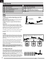
Page 18: ...y not to get the aircraft too high or far away It will make it difficult to see Make small and gentle stick movements to see how the aircraft responds Flying with the nose pointed toward you is one of the hardest things to do when learning to fly Practice flying in large circles high off the ground If you lose orientation of the aircraft press and hold the PANIC button and the aircraft will return...

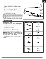
Page 19: ...bout 100 Having an experienced flight instructor trim your aircraft during the first flight is recommended Aircraft Drift Trim Required Elevator Elevator Trim Elevator Trim Aileron Aileron Trim Aileron Trim Rudder Rudder Trim Rudder Trim Land the aircraft 1 Reduce the throttle to around 50 to slow the airspeed 2 Fly the aircraft downwind past the end of the runway 3 Turn the aircraft into the wind...

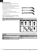
Page 20: ... should be set to Experienced mode position 2 before manually adjusting the trim settings The aircraft should be kept still while performing manual adjustment of trim With the trim settings from the trim flight still set in the transmitter take note of the positions of each of the control surfaces one at a time Adjust the clevis on each control surface to position the surface the same as it was wi...

Page 21: ... 1 2 Aircraft will not climb Battery is not fully charged Fully charge battery before flying Elevator may be trimmed down Adjust elevator trim up Rotor damaged Land immediately replace Rotor Aircraft is difficult to launch in the wind Launching the aircraft down wind or into a cross wind Always launch the aircraft directly into the wind Flight time is too short Battery is not fully charged Recharg...

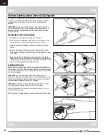
Page 22: ... with a click 5 Place the aircraft on its landing gear and connect LAS connector to Channel 7 on the flight controller For correct polarity of the plug ensure that the orange not brown signal wire B is facing towards the front of the aircraft when plugged into the flight controller Landing with LAS Reduce throttle keep the wings level and slowly reduce the altitude of the aircraft When the aircraf...

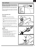
Page 23: ... front of the rotor is installed facing the nose of the aircraft Use a hex wrench to tighten the spinner on the rotor and collet Ensure the spinner is fully connected for safe operation Ensure no wiring is pinched by any of the power components Correctly align and install wing to fuselage using 4 wing screws A Wiring not shown Service and Repairs Power Components Service NOTICE After any impact or...

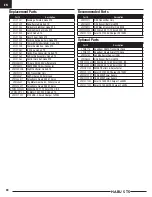
Page 24: ...Gears SA381 Servo SPMSA382 13g Metal Gear Servo 240mm Lead SPMSA3821 Servo Arms Gears SA382 Servo SPMX40003S30 4000mAh 3S 11 1V Smart 30C IC3 SPMXAM1100 BL Motor 2847 3200 Habu STS SPMXC1020 S120 USB C Smart Charger 1x20W Part Description SPMR1010 DXS Transmitter Only SPMR8000 DX8 Transmitter Only MD2 SPMR9910 DX9 Black Transmitter Only MD2 SPMX40003S30 4000mah 3S 11 1V Smart 30C IC3 SPMXC1010 Sma...

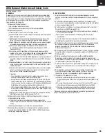
Page 25: ...hows or model demonstrations unless a The aircraft control system and pilot skills have successfully demonstrated all maneuvers intended or anticipated prior to the specific event b An inexperienced pilot is assisted by an experienced pilot 4 When and where required by rule helmets must be properly worn and fastened They must be OSHA DOT ANSI SNELL or NOCSAE approved or comply with comparable stan...

Page 26: ...and Service Contact Information section to speak with a Product Support representative Inspection or Services If this Product needs to be inspected or serviced and is compliant in the country you live and use the Product in please use the Horizon Online Service Request submission process found on our website or call Horizon to obtain a Return Merchandise Authorization RMA number Pack the Product s...

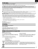
Page 27: ...conditions 1 This device may not cause harmful interference and 2 this device must accept any interference received including interference that may cause undesired operation CAUTION Changes or modifications not expressly approved by the party responsible for compliance could void the user s authority to operate the equipment This product contains a radio transmitter with wireless technology which ...

Page 28: ...r registered trademarks of Horizon Hobby LLC The Spektrum trademark is used with permission of Bachmann Industries Inc Futaba is a registered trademark of Futaba Denshi Kogyo Kabushiki Kaisha Corporation of Japan All other trademarks service marks and logos are property of their respective owners US 8 672 726 US 9 056 667 US 9 753 457 US 10 078 329 US 9 930 567 US 10 419 970 CN201721563463 4 Other...

Reviews: