EN
23
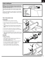
Disassembly
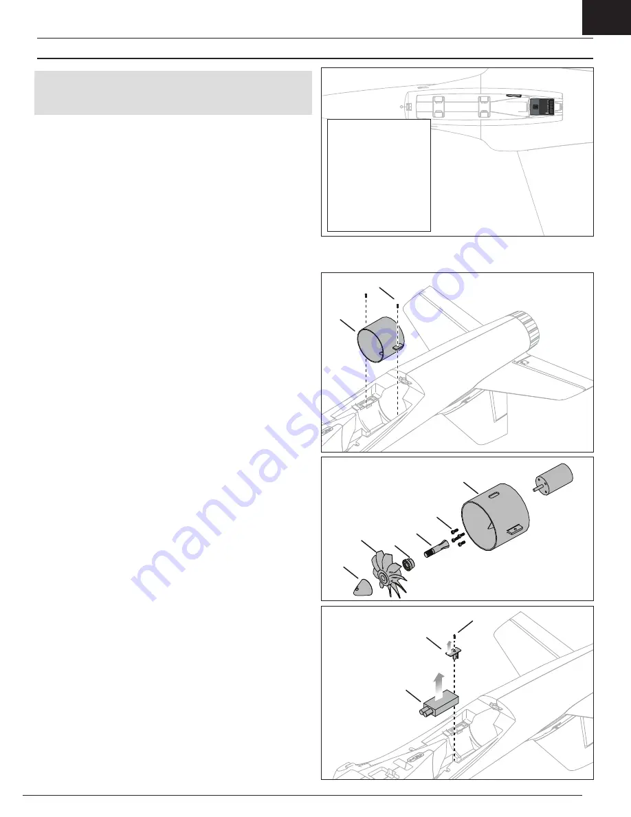
1. Remove the four screws and carefully remove the wing.
2. Remove the two screws (
A
) from the fan unit mounting tabs.
3. Pull the fan unit (
B
) out of the fuselage and disconnect the motor leads from
the ESC.
4. Remove the spinner (
C
) from the rotor by using a hex wrench inserted
through the spinner holes and turning the spinner from the motor shaft
adapter.
5. Remove the rotor (
D
), rotor backplate (
E
) and motor shaft adapter (
F
).
6. Remove the four screws (
G
) to remove the motor from the fan shroud (
H
).
7. Remove the screw (
I
) and plastic ESC clip (
J
) .
8. Disconnect the throttle lead from the receiver and pull the ESC (
K
) from the
fuselage, taking note of the routing of the power and throttle leads through
the fuselage.
Assembly
Assemble in reverse order
.
• Assemble in reverse order.
• Correctly align and connect the motor wire colors with the ESC wires.
• Ensure the ESC is installed correctly and secured
to the fuselage using clip and screw.
• Ensure the front of the rotor is installed facing the nose of the aircraft.
• Use a hex wrench to tighten the spinner on the rotor and collet.
• Ensure the spinner is fully connected for safe operation.
• Ensure no wiring is pinched by any of the power components.
• Correctly align and install wing to fuselage using 4 wing screws.
A
Wiring not shown.
Service and Repairs
Power Components Service
NOTICE:
After any impact or replacement, always ensure the receiver and
flight controller are secure in the fuselage. If you replace the receiver or flight
cotroller, install the new receiver in the same orientation and manner as the
original receiver or damage may result.
Repairs to the wings and fuselage of this aircraft can be made easily using
virtually any adhesive (hot glue, regular CA (cyanoacrylate adhesive), epoxy,
etc).
When parts are not repairable, see the Replacement Parts List for ordering by
item number. For a listing of all replacement and optional parts, refer to the list
at the back of this manual.
B
J
K
I
C
D
F
E
G
Wiring not shown.
Wiring not shown.
H
BIND
1 = ESC (PWM)
2 = Ailerons
3 = Elevator
4 = Rudder
5 = Nose wheel
6 = ESC (Telemetry)
7 = Open/Optional LAS
8 = Aux 2


