EN
9
E
2.5 X 8mm (2)
C
D
2.5 X 8mm (3)
G
F
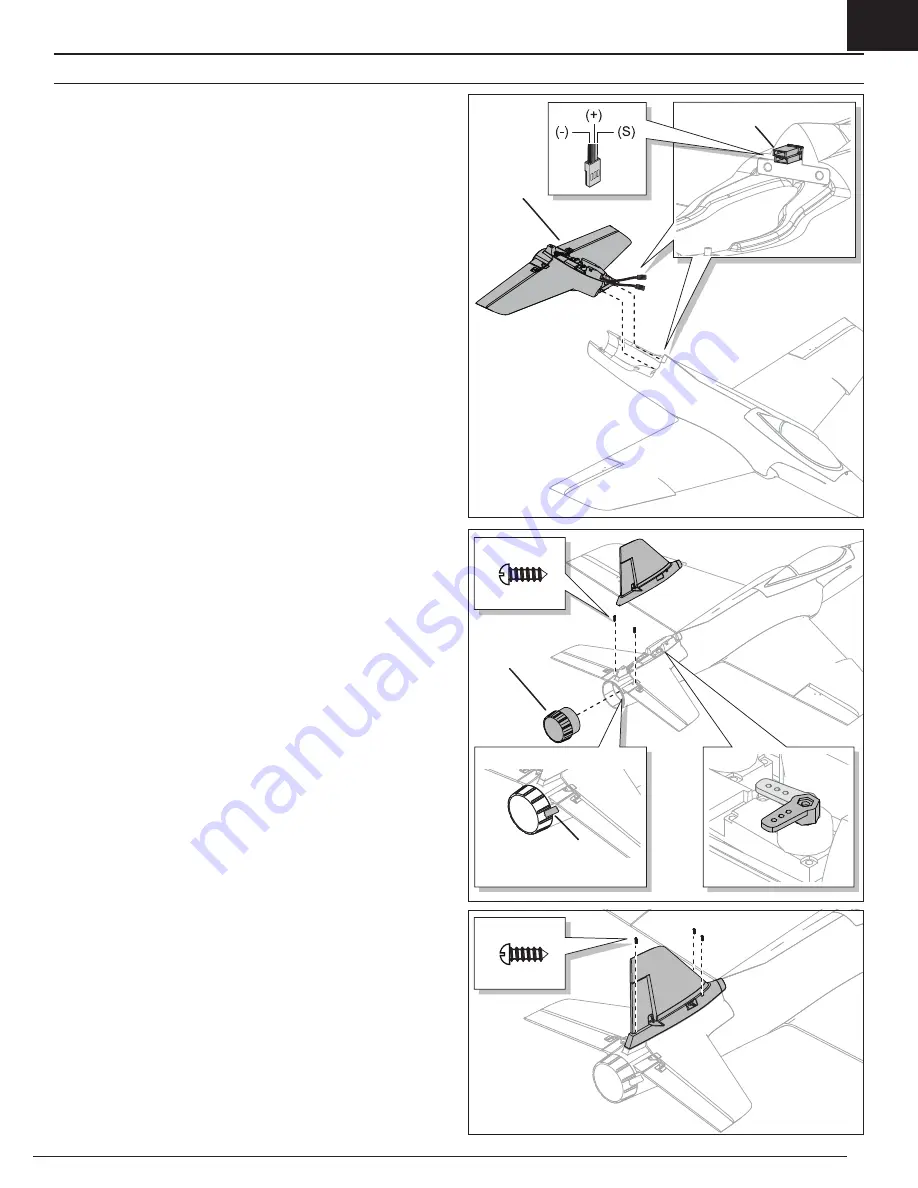
Tail Installation
1. Loosely align the horizontal stabilizer assembly (
A
) on the rear of
the fuselage.
2. Correctly connect the rudder and elevator servo connectors (
B
) to the
marked connectors in the fuselage. Orange is the signal wire (S) red is
positive (+) brown is negative (-).
IMPORTANT:
Ensure no wires are pinched or damaged when the tail unit is
attached to the fuselage.
3. Install and secure the tail assembly on the top of the rear fuselage using
two screws (
C
).
4. Manually position the rudder servo arm as shown (
D
).
5. Align and press the tail cone (
E
) on the rear of the fuselage and secure the
cone in place with included tape (
F
).
6. Align the vertical fin with the fuselage and guide the rudder servo arm
through the hole of the vertical fin base.
7. Secure the vertical fin to the fuselage with three 2.5 x 8mm screws (
G
).
8. Attach the Z-bend of the linkage (
H
) in the second hole of the rudder servo
arm (
I
) (the hole next to the outermost hole).
9. Attach the linkage clevis (
J
) to the outer hole of the rudder control horn (
K
).
Ensure the tube (
L
) tightens the clevis on the control horn.
Where needed, disassemble in reverse order.
A
B
Assemble the Aircraft


