background image

EN

Float Assembly and Installation

1.  Remove the screw on the bottom of the fuselage, and remove the landing gear 

cover.

2.  Loosen the nose wheel assembly screw, and remove the nose wheel assembly 

from the nose wheel steering bracket.

3.  Loosen the six 2mm x 10mm mounting screws from the landing gear mounting 

clamps. Remove the mounting clamps (screws attached) and set them aside.

4.  Install the front and rear float struts in the fuselage. The float struts angle down at 

the ends; the wheel strut is straight out, away from the plane.

5.  Reinstall the landing gear cover and tighten the fuselage screw.
6.  Install the floats and the spreader bars onto the struts, using the plastic clamps and 

the 2mm x 10mm screws to secure each clamp.

7.  Install the steering wire, slipping the z-bend into the steering arm and snapping the 

rear clip into the water rudder clevis.

8.  Secure the pushrod sleeve to the rear spreader bar with the included zip tie.

Tip: 

If you removed the steering arm for the water rudder for flying with wheels, 

reinstall it for flying with floats.

Disassemble in reverse order.

NOTICE:

 If installing floats, always recheck the center of gravity before 

attempting to fly. Failure to do so may result in a crash.

14

Twin Otter 1.2m

Flying off water poses a higher risk because piloting errors or water conditions 

can cause the aircraft to become stranded. Only fly from the water when a level of 

comfort has been achieved flying the aircraft from the ground. 

Pre-Flight

Ensure the optional floats are secure on the fuselage and the water rudder is correctly 

connected and operating with the main rudder before putting the aircraft in the water. 

Select an area to fly that does not have water currents, salt water, or debris. Look around 

the flight area and be aware of trees, docks, buoys, or other obstacles. Always fly with a 

spotter and avoid swimmers, boaters, people fishing, and people on the beach.

Taxiing

When taxiing, use low throttle settings and the rudders to steer. Hold up elevator to 

help keep the rudder in the water and the nose of the floats above the surface. Steer 

into the wind when turning, and crab into the wind if crosswind taxiing is required. 

When turning or crabbing into the wind, apply aileron against the wind to keep the 

upwind side of the wing down and prevent the aircraft from being flipped over. Do not 

apply down elevator when the airplane is taxiing or during the takeoff run.

On Step

When speed increases with throttle, the floats will rise out of the water and begin 

to plane on the surface of the water, riding “on step.” The floats will come on step 

at a speed below flight speed, this is a transitional phase when the aircraft is not 

up to flight speed yet. This is considered a high speed taxi. Do not attempt to take 

off as soon as the aircraft comes on step. Use low to medium throttle and hold up 

elevator to manage speed on the water during a high speed taxi.

Takeoff

To lift off from the water, set the flaps to the takeoff position, hold up elevator and 

accelerate the aircraft to bring it on step. Relax the up elevator as the airplane comes  

on step and accelerate to flight speed with full throttle. When the aircraft is travelling 

at a sufficient speed, pull back slightly on the elevator to rotate for liftoff. 

Landing

To land on the water, set the flaps to the landing position, and fly into the wind. 

Reduce the throttle to a low setting but keep some power during the approach. As 

the aircraft settles into ground effect, reduce the throttle fully and hold up elevator 

to flare. Hold up elevator through the touch down and as the airplane decelerates 

on the water. 

WARNING: 

Never attempt to retrieve a downed aircraft by swimming 

unless you are sufficiently trained and/or there is another person available 

to respond in the case of an emergency.

CAUTION:

 Have a plan for retrieval in the event the airplane becomes 

stranded. Never retrieve a downed model in the water alone. 

CAUTION:

 If at any time water splashes in the fuselage while flying from 

water, bring the airplane to shore, open the battery hatch and immediately 

remove any water that may have gotten in the fuselage. Leave the battery hatch 

open overnight to let the inside dry out and to prevent moisture damage to the 

electronic components. Failure to do so could cause the electronic components 

to fail, which could result in a crash.

TIP: 

Use a fishing pole with heavy line as a retrieval tool. Attach a tennis ball to the 

line, and throw the ball past a stranded aircraft to retrieve it.

Flying Off Water

Summary of Contents for E-flite Twin Otter 1.2m

Page 1: ...Instruction Manual Bedienungsanleitung Manuel d utilisation Manuale di Istruzioni SAFE Select Technology Optional Flight Envelope Protection Twin Otter 1 2m ...

Page 2: ...roduct literature to indicate various levels of potential harm when operating this product WARNING Procedures which if not properly followed create the probability of property damage collateral damage and serious injury OR create a high probability of superficial injury CAUTION Procedures which if not properly followed create the probability of physical property damage AND a possibility of serious...

Page 3: ... Assembly 4 Receiver Installation PNP 6 Transmitter Setup BNF 6 Battery Installation and ESC Arming 7 Center of Gravity 7 Transmitter and Receiver Binding Switching ON and OFF SAFE Select BNF 8 SAFE Select Switch Designation 9 Control Surface Centering 9 Control Surface Direction 10 Dual Rates and Control Throws 10 AS3X Control Direction Test BNF 11 In Flight Trimming BNF 11 Flying Tips and Repair...

Page 4: ...m Preflight SAFE Select Technology BNF Basic The BNF Basic version of this airplane includes SAFE Select technology which can offer an extra level of protection in flight Use the following instructions to make the SAFE Select system active and assign it to a switch When enabled SAFE Select prevents the airplane from banking or pitching past predetermined limits and automatic self leveling keeps th...

Page 5: ...r 4 Rudder 5 LED Lights 6 Flaps Propeller Installation WARNING Do not install the propeller until all system setups are complete Failure to heed this warning could result in severe personal injury 1 Determine which propeller matches each image and install as shown 2 Install the left propeller T7056C on the left propeller adaptor Install the right propeller T7056CR on the right propeller adaptor Ti...

Page 6: ...e Refer to spektrumrc com for the appropriate download setup DX6i 1 Go to the SETUP LIST MENU 2 Set MODEL TYPE ACRO 3 Go to ADJUST LIST MENU 4 Set TRAVEL FLAPS 100 100 5 Set FLAPS Norm 100 Flap Elev 0 LAND 100 Flap Elev 35 DX7S DX8 1 Go to the SYSTEM SETUP 2 Set MODEL TYPE AIRPLANE 3 Set WING TYPE 1 AIL 1 FLAP 4 Go to the FUNCTION LIST 5 Set FLAP SYSTEM Choose Flap NORM 100 FLAP MID 0 FLAP 25 Elev...

Page 7: ...ndicate the ESCs are armed CAUTION Always keep hands away from the propeller When armed the motor will turn the propeller in response to any throttle movement 5 Keep the aircraft immobile and away from wind or the system will not initialize The motor will emit two even tones when the battery is connected and the ESC has a throttle signal The receiver LED will illuminate orange when it is initializ...

Page 8: ...ound the receiver will retain its bind settings for that transmitter until it has been intentionally changed even when power is cycled ON and OFF Repeat the binding process as necessary SAFE Select OFF Indication Every time the receiver is powered ON the surfaces will cycle back and forth once to indicate that SAFE Select has been switched OFF The throttle will not arm if the transmitter s throttl...

Page 9: ...If the aircraft is bound with SAFE select OFF the aircraft will be in AS3X mode exclusively IMPORTANT Before assigning your desired switch ensure that the travel for that channel is set at 100 in both directions and the aileron elevator rudder and throttle are all on high rate with the travel at 100 CAUTION Keep all body parts well clear of the propeller and keep the aircraft securely restrained i...

Page 10: ...ntrol directions Ailerons 1 Move the aileron stick to the left The right aileron should move down and the left aileron up which will cause the aircraft to bank left 2 Move the aileron stick to the right The right aileron should move up and the left aileron down which will cause the aircraft to bank right Aileron stick Rudder stick Elevator stick Elevators 1 Pull the elevator stick back The elevato...

Page 11: ...rol surfaces do not respond as shown do not fly the aircraft Refer to the receiver manual for more information Once the AS3X system is active control surfaces may move rapidly This is normal AS3X remains active until the battery is disconnected During your first flight trim the aircraft for level flight at 1 2 throttle with flaps up Make small trim adjustments with your transmitter s trim switches...

Page 12: ...ttery is discharged too much per cell it will not hold a charge The ESC protects the flight battery from over discharge using Low Voltage Cutoff LVC Before the battery charge decreases too much LVC removes power supplied to the motor Power to the motor reduces showing that some battery power is reserved for flight control and safe landing Disconnect and remove the Li Po battery from the aircraft a...

Page 13: ...flight battery before performing motor service Disassembly 1 Remove the spinner screw and spinner from the propeller shaft 2 Remove the propeller nut The right propeller nut for prop T7056CR is reverse rotation 3 Remove the propeller 4 Remove the two screws from the sides of the cowling and remove the cowling from the nacelle 5 Remove top and bottom set screws 6 Disconnect the motor wires from the...

Page 14: ...is required When turning or crabbing into the wind apply aileron against the wind to keep the upwind side of the wing down and prevent the aircraft from being flipped over Do not apply down elevator when the airplane is taxiing or during the takeoff run On Step When speed increases with throttle the floats will rise out of the water and begin to plane on the surface of the water riding on step The...

Page 15: ...LA111 Li Po Cell Voltage Checker DYN1405 Li Po Charge Protection Bag Large DYN1400 Li Po Charge Protection Bag Small SPMR12000 iX12 12 Channel Transmitter Only SPMR6750 DX6 Transmitter Only MD2 G3 SPMR8000 DX8 Transmitter Only MD2 SPMR8100 DX8e 8CH Transmitter Only SPMR9910 DX9 Black Transmitter Only MD2 SPMX32003S30 11 1V 3200mAh 3S 30C Smart LiPo IC3 SPMXC1000 Smart S1200 DC Charger 1x200W SPMXC...

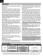
Page 16: ... air shows or model demonstrations unless a The aircraft control system and pilot skills have successfully demonstrated all maneuvers intended or anticipated prior to the specific event b An inexperienced pilot is assisted by an experienced pilot 4 When and where required by rule helmets must be properly worn and fastened They must be OSHA DOT ANSI SNELL or NOCSAE approved or comply with comparabl...

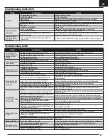
Page 17: ...bind transmitter to the aircraft and remove the bind plug before cycling power Aircraft bound to different model memory Model MatchTM radios only Select correct model memory on transmitter Flight battery Transmitter battery charge is too low Replace recharge batteries Transmitter may have been bound to a different aircraft using different DSM protocol Bind aircraft to transmitter Control surface d...

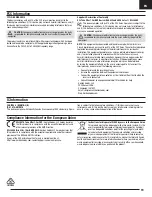
Page 18: ...section to speak with a Product Support representative Inspection or Services If this Product needs to be inspected or serviced and is compliant in the country you live and use the Product in please use the Horizon Online Service Request submission process found on our website or call Horizon to obtain a Return Merchandise Authorization RMA number Pack the Product securely using a shipping carton ...

Page 19: ...ed to try to correct the interference by one or more of the following measures Reorient or relocate the receiving antenna Increase the separation between the equipment and receiver Connect the equipment into an outlet on a circuit different from that to which the receiver is connected Consult the dealer or an experienced radio TV technician for help Horizon Hobby LLC 2904 Research Rd Champaign IL ...

Page 20: ...s of Horizon Hobby LLC The Spektrum trademark is used with permission of Bachmann Industries Inc Futaba is a registered trademark of Futaba Denshi Kogyo Kabushiki Kaisha Corporation of Japan All other trademarks service marks and logos are property of their respective owners US 8 672 726 US 9 056 667 US 9 753 457 US 10 078 329 US 9 930 567 US 10 419 970 www horizonhobby com Updated 01 20 59818 1 E...

Reviews: