EN
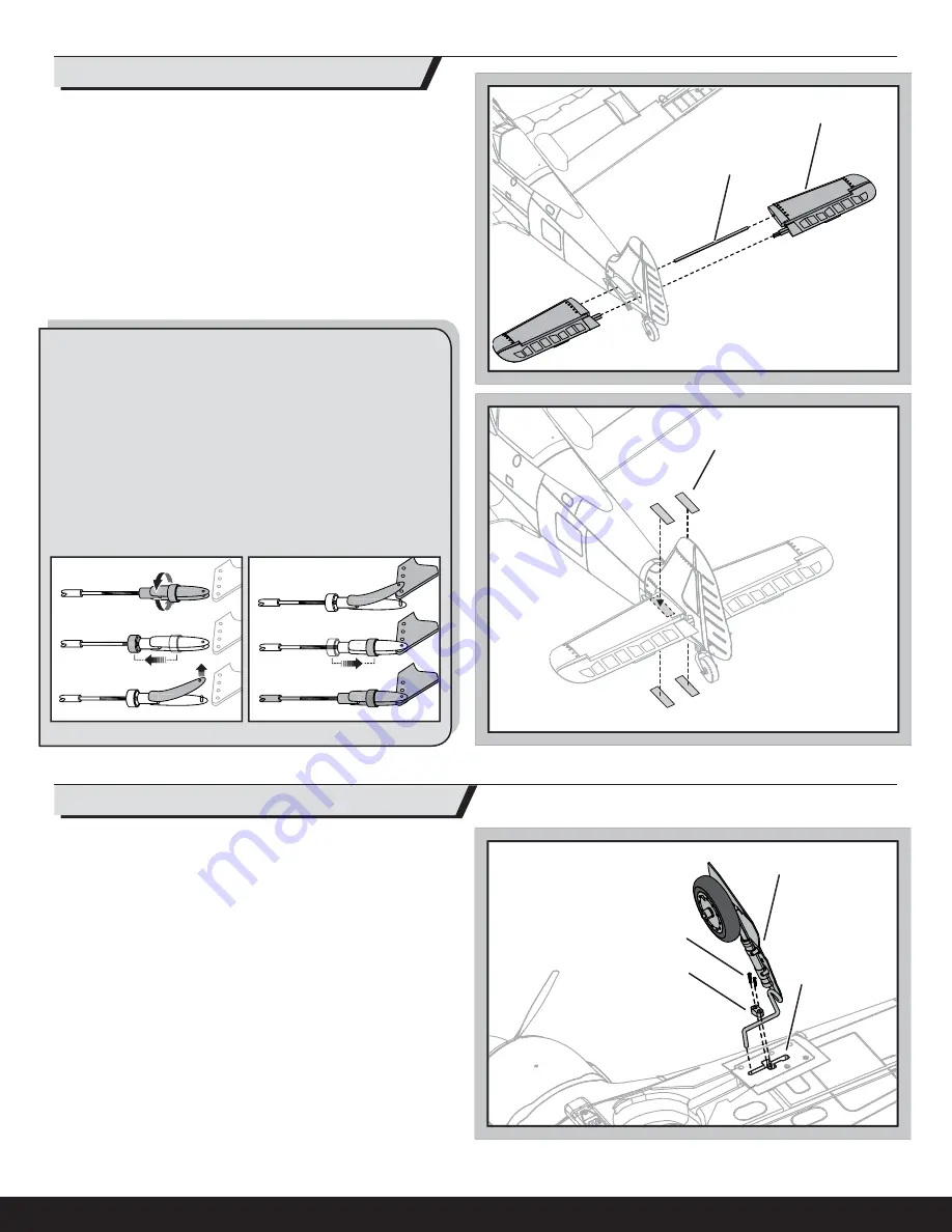
Fixed Landing Gear Installation
1. Install the left and right fi xed landing gear (
A
) in the respective mounting
plates (
B
).
2. Install the left and right covers (
C
) in the respective mounting plates using
2 screws (
D
) each.
When needed, disassemble in reverse order.
A
B
C
D
A
B
C
1.
2.
3.
4.
5.
6.
1. Slide the horizontal tail tube (
A
) into the hole in the rear of the fuselage.
2. Install the left and right horizontal tails (
B
) onto the fuselage as shown.
Ensure the control horn faces down.
3. Apply 4 pieces of tape (
C
) to the fuselage mounts (one on the top and bot-
tom of each half of the horizontal tail).
4. Attach the clevis to the elevator control horn (see instructions for clevis
connection).
When needed, disassemble in reverse order.
Clevis Installation
Tip:
Turn the clevis on the linkage to change the length of the linkage
between the servo arm and the control horn.
• Pull the tube from the clevis to the linkage.
• Carefully spread the clevis, then insert the clevis pin into the desired
hole in the control horn.
• Move the tube to hold the clevis on the control horn.
After binding a transmitter to the aircraft receiver, set the trims and
sub-trims to 0, then adjust the clevises to center the control surfaces.
Horizontal Tail Installation
9


