GAS ENGINE INSTALLATION
1.
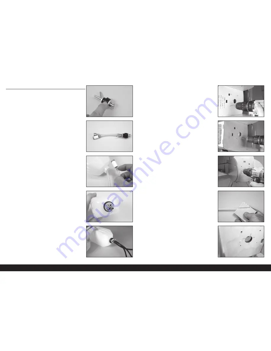
Prepare the stopper assembly by placing small amounts of solder on
the end of the tubes shown. This will help keep the fuel lines secure
when installed.
Use hemostats to act as a heat-sink to
avoid melting the rubber stopper.
2.
Cut a piece of fuel tubing that will result in the end of the clunk
being 5 inches (127mm) from the back of the aluminum plate.
Secure the tubing to the clunk and stopper using thin wire. This will
keep the tubing from sliding loose inside the tank. Make sure to use
the clunk supplied with your engine.
A second clunk can be installed to provide
a line to fuel/defuel your aircraft.
4.
Mark the lines from the tank so the fuel lines can be identifi ed from
outside the tank. Tighten the screw in the stopper using a #1 Phillips
screwdriver.
Check that both clunks can move freely inside the tank.
If not, adjust the tubing from outside the tank so they can
move freely to ensure consistent fuel flow to the engine.
5.
Secure an 8-inch (200mm) fuel line to the fi ll, vent and clunk tubes
of the fuel tank. Tie wraps can also be used to secure the fuel lines
as an alternative to wire ties.
3.
Insert the clunks into the tank. Install the larger clunk, then the small
clunk.
6.
Place the mounting template on the fi rewall. Use low-tack tape to
hold the template in position. Use a drill and 3/32-inch (2.5mm) drill
bit to drill the four holes in the fi rewall to attach the motor box.
When using power systems other than the recommended
choices, we advise using the mounting template as a test
to ensure hole alignment before drilling the firewall.
7.
Remove the template from the fuselage. Use a drill and 9/32-inch
(7mm) drill bit to enlarge the holes from the previous step.
Drilling increasingly larger holes allows the ability to
check the alignment of engine mounting holes. It also
helps reduce splintering of the firewall material.
9.
Use medium grit sandpaper to roughen the outside edge of the
throttle pushrod tube. Cut the tube to a length of 7 inches (178mm)
using a hobby knife and #11 blade
10.
Insert the tube in the hole. Leave 1/4-inch (6mm) of the tube
protruding from the fi rewall. Use medium CA to glue the tube in the
fi rewall.
8.
Use the template to locate and drill the hole for the throttle pushrod
using a drill and 9/64-inch (3.5mm) drill bit.
Make sure the throttle tube location matches the engine
selection. It may be necessary to drill the hole in a
different location than recommended by the template.
28
EN


