5
EN
LOSI
®
22S NO PREP DRAG: 1/10 SCALE 2WD RTR • INSTRUCTION MANUAL
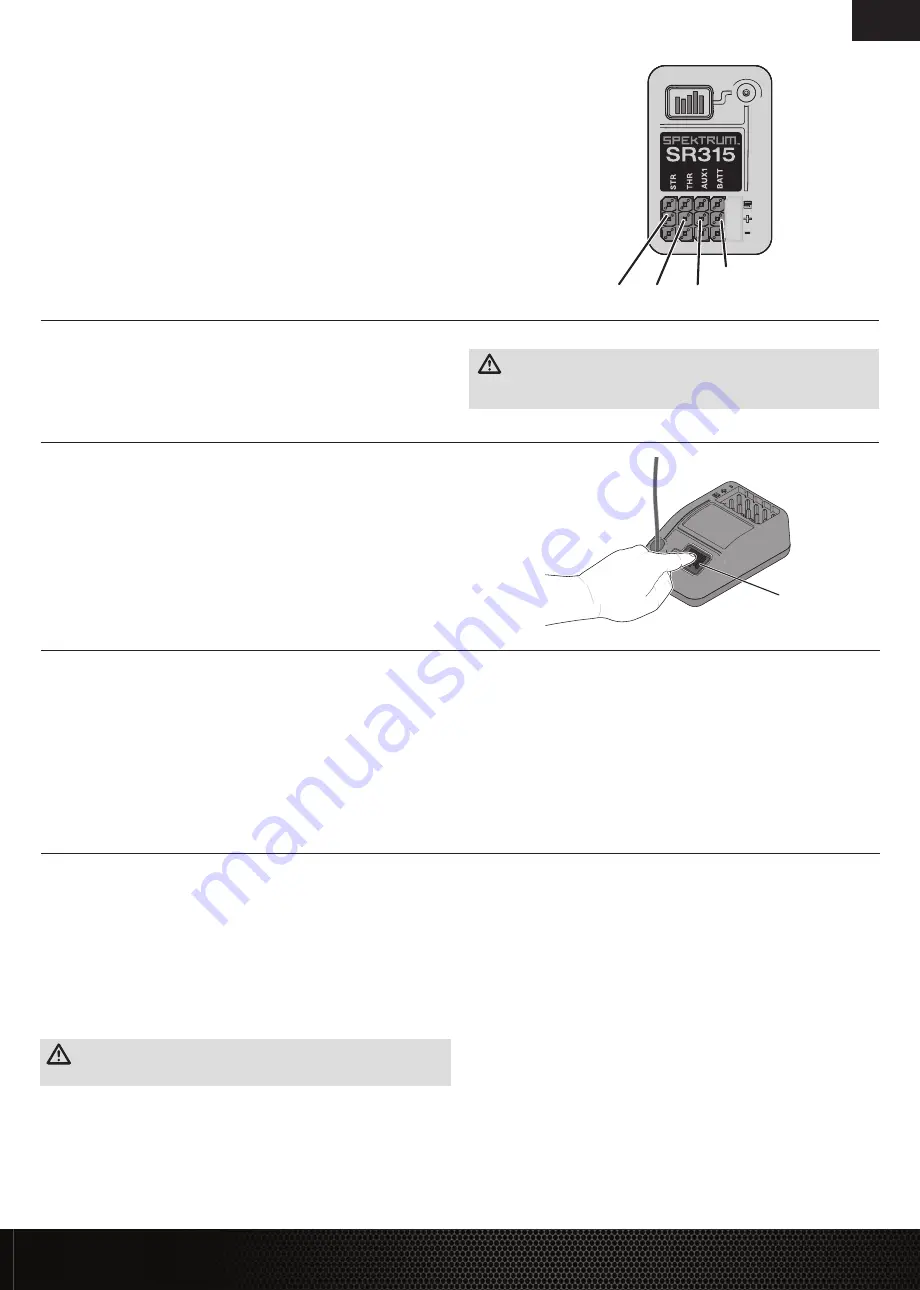
Binding is the process of programming the receiver to recognize the GUID (Globally Unique
Identifier) code of a single specific transmitter.
1. Press and hold the bind button.
2. Power ON the receiver. The orange LED will begin to flash.
3. Set the trims and control positions at the desired failsafe settings.
4. Power ON the SLT3 transmitter.
5. When the transmitter’s orange LED remains lit, it is connected to SR315 receiver.
You must rebind when:
• Different failsafe positions are desired (e.g., when throttle or steering reversing has
changed).
• Binding the receiver to a different transmitter.
The servo travel on the Steering and Throttle channels can be adjusted through a special pro-
gramming mode in the transmitter.
1. Begin with the transmitter binding process to the receiver complete. Power ON the receiver.
2. Hold full right and full brake while powering the transmitter ON to put the transmitter into
programming mode.
The LED on the transmitter will flash 4 times to indicate it is in programming mode.
3. Turn and hold the wheel full left to set the travel limit for that direction, Press the A button
to increase travel, press the B button to reduce travel. The LED will flash once with every
change. Return the wheel to center to set the travel value.
IMPORTANT:
If the value has reached the maximum or minimum that can be accepted,
the LED will not flash with further input.
4. Turn the wheel to the right and repeat the process to set the steering travel to the right.
5. For electric vehicles, power the Transmitter OFF to save the settings. Calibrate your ESC to
the default throttle travel.
6. For fuel powered vehicles, set the throttle travel without the engine running; After setting
steering travel, you can set throttle travel with the same process. Pull and hold full throttle,
adjust travel with the A and B buttons, return to center to set the value.
7. Push full brake, adjust travel with the A and B buttons, return to center
8. Power the transmitter OFF to save the values.
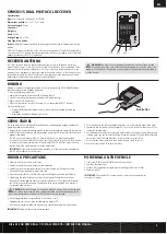
Bind Button
SPMSR315 DUAL PROTOCOL RECEIVER
BINDING
Specifications
Type:
Dual Protocol 3 Ch Receiver* (SLT/DSMR)
Dimensions (LxWxH):
32.5 x 21.5 x 12.4mm
Antenna Length:
90mm
Channels:
3
Weight:
6g
Band:
2.4GHz
Voltage Range:
3.5–9.6V
Bind Type: Bind Button
Failsafe:
Hold the steering wheel and throttle trigger in the desired failsafe positions during
binding
*SPMSR315 receivers included with the SLT3 transmitter include SLT and DSMR compatibility.
If you have an SR315 receiver that was purchased by itself, you may need to install a firmware
update to make your SR315 SLT compatible.
STR
THR
BATT
AUX 1
The SR315 receivers feature a coaxial antenna design for easy installation in almost any
model. Think of the last 1 inch (32mm) on the tip of the antenna as the active portion of the
antenna, the coaxial portion leading up to it is just an extension. Install the antenna so the
active portion is positioned as high as possible in the vehicle, and not “in the shadow” of any
carbon fiber or metal. The case of the receiver can accept an antenna tube directly, making
optimal antenna placement easy (antenna tube not included).
WARNING:
Do not kink, cut or damage the antenna wire. The antenna is made
of a coaxial wire; if the outer sheath becomes damaged, the receiver will not work
properly. If the antenna is damaged in any way, replace the antenna before attempting to
use the receiver.
RECEIVER ANTENNA
SERVO TRAVEL
DRIVING PRECAUTIONS
• Maintain sight of the vehicle at all times.
• Routinely inspect the vehicle for loose wheel hardware.
• Routinely inspect the steering assembly for any loose hardware. Driving the vehicle
off-road can cause fasteners to loosen over time.
• Do not drive the vehicle in tall grass. Doing so can damage the vehicle or electronics.
• Stop driving the vehicle when you notice a lack of power. Driving the vehicle when
the battery is discharged can cause the receiver to power off. If the receiver loses power,
you will lose control of the vehicle. Damage due to an over-discharged Li-Po battery is
not covered under warranty.
CAUTION:
Do not discharge a Li-Po battery below 3V per cell. Batteries discharged
to a voltage lower than the lowest approved voltage may become damaged, result-
ing in loss of performance and potential fire when batteries are charged.
• Do not apply forward or reverse throttle if the vehicle is stuck.
Applying throttle in this instance can damage the motor or ESC.
• After driving the vehicle, allow the electronics to cool before driving the vehicle again.
IMPORTANT:
Keep wires away from all moving parts.
POWERING ON THE VEHICLE
1. Center the ST TRIM and TH TRIM dials on the transmitter.
2. Power on the transmitter.
3. Install a fully charged battery pack per the
Installing the Battery
section.
4. Power on the ESC.
IMPORTANT:
The vehicle MUST remain on a flat, level surface and motionless
for at least 5 seconds.


