background image

8

EN

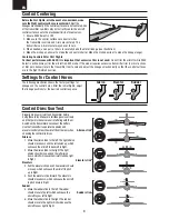
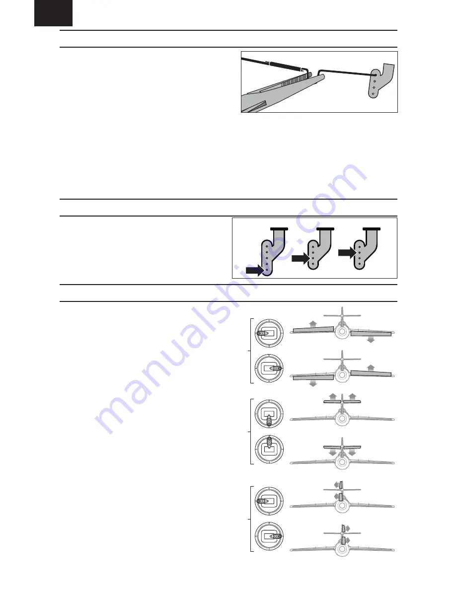
Settings for Control Horns

The following illustration shows the factory settings for 
linkages on the control horns. After the initial fl ights, adjust 
the linkage positions for the desired control response.

Aileron Elevator 

 Rudder

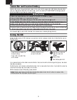
Before the fi rst fl ights, or in the event of an accident, make 
sure the fl ight control surfaces are centered.

 Adjust the 

linkages mechanically if the control surfaces are not centered. Use 
of the transmitter sub-trims may not correctly center the aircraft 
control surfaces due to the mechanical limits of linear servos.

1. Ensure SAFE Select is OFF.
2. Make sure the control surfaces are neutral when 

the transmitter controls and trims are centered. The 
transmitter sub-trim must always be set to zero.

3. When needed, use a pair of pliers to carefully bend the metal linkage (see illustration).
4. Make the U-shape narrower to make the connector shorter. Make the U-shape wider to make the linkage longer.

Centering Controls After First Flights

For best performance with AS3X, it is important that excessive trim is not used.

 Do not trim the aircraft while SAFE 

Select is active. Always trim the aircraft in AS3X mode. If the model requires excessive transmitter trim (4 or more clicks 
of trim per channel), return the transmitter trim to zero and adjust the linkages mechanically so that the control surfaces 
are in the fl ight trimmed position. 

Control Centering

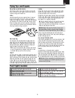
Control Direction Test

Properly bind your aircraft and transmitter before 
doing these tests. Make sure tail linkages move freely 
and that paint or decals are not interfering with them.
Switch on the transmitter and connect the battery. 
Use the transmitter to operate the aileron and 
elevator controls. View the aircraft from the rear when 
checking the control directions.

Ailerons

1.  Move the aileron stick to the left. The right aileron 

should move down and the left aileron up, which 
will cause the aircraft to bank left in fl ight.

2.  Move the aileron stick to the right. The right 

aileron should move up and the left aileron 
down, which will cause the aircraft to bank right 
in fl ight.

Elevators

3.  Pull the elevator stick back. The elevators should 

move up, which will cause the aircraft to pitch 
up in fl ight.

4.  Push the elevator stick forward. The elevators 

should move down, which will cause the aircraft 
to pitch down in fl ight.

Rudder

5.  Move the rudder stick to the left. The rudder 

should move to the left, which will cause the 
aircraft to yaw left in fl ight.

6.  Move the rudder stick to the right. The rudder 

should move to the right, which will cause the 
aircraft to yaw right in fl ight.

Aileron stick

Elevator stick

Rudder stick

Summary of Contents for UMX MiG 15 DF

Page 1: ...Instruction Manual Bedienungsanleitung Manuel d utilisation Manuale di Istruzioni SAFE Select Technology Optional Flight Envelope Protection UMX MiG 15 DF ...

Page 2: ...ibility and performance of counterfeit products or products claiming compatibility with DSM or Spektrum technology Age Recommendation Not for children under 14 years This is not a toy Safety Precautions and Warnings WARNING Read the ENTIRE instruction manual to become familiar with the features of the product before operating Failure to operate the product correctly can result in damage to the pro...

Page 3: ...light Checklist 9 Service of Power Components 10 AS3X Troubleshooting Guide 11 Troubleshooting Guide 11 Replacement Parts List 12 Recommended Parts List 12 Limited Warranty 13 Warranty and Service Contact Information 14 FCC Information 14 IC Information 14 Compliance Information for the European Union 15 Flying Weight Motor BL180m Ducted Fan Motor 13500Kv EFLM30180MDFE Fan Delta V 180m 28mm EDF Un...

Page 4: ...battery 4 Install the optional landing gear 5 Program your transmitter 6 Install the fully charged flight battery in the aircraft 7 Check the center of gravity CG 8 Bind the aircraft to your transmitter 9 Make sure all linkages move freely 10 Perform the control direction test 11 Adjust the flight controls and transmitter as needed 12 Perform a radio system range test 13 Find a safe open area to fly ...

Page 5: ...ys rebind the transmitter and receiver to set the desired failsafe positions If your transmitter allows it enable the throttle cut feature Always engage throttle cut before approaching the aircraft Dual Rates Low rate is recommended for the initial flights NOTICE To ensure AS3X technology functions properly do not lower rate values below 50 NOTICE If oscillation occurs at high speed refer to the T...

Page 6: ...C Arming the ESC also occurs after binding as previously described but subsequent connection of a flight battery requires the steps below Lower throttle and throttle trim to lowest settings Power on the transmitter then wait 5 seconds Install the flight battery and connect it to the ESC Keep plane immobile and away from wind for 5 seconds Series of tones Slow flashing green LED Binding Procedure 1 Re...

Page 7: ...he aircraft level To activate SAFE Select flip the Gear channel switch to position 0 Return the Gear switch to position 1 to turn OFF SAFE Select and fly with just the assistance of AS3X technology If you become disoriented or the aircraft is in a confusing attitude flip the Gear switch to position 0 and release the sticks With the aileron elevator and rudder sticks in the neutral position SAFE Selec...

Page 8: ...licks of trim per channel return the transmitter trim to zero and adjust the linkages mechanically so that the control surfaces are in the flight trimmed position Control Centering Control Direction Test Properly bind your aircraft and transmitter before doing these tests Make sure tail linkages move freely and that paint or decals are not interfering with them Switch on the transmitter and connect...

Page 9: ...rcraft pointed into the wind Slowly lower the throttle while easing back on the elevator to bring the aircraft gently down on the main wheels or to smoothly belly land TIP We recommend that you do not install the optional nose cannons for belly landings Installation of this option could prevent smooth belly landings on grass and could cause damage to the aircraft NOTICE Always fully lower the thro...

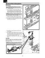
Page 10: ... the 4 screws D and fan unit E from the upper fuselage 6 Put a small flat blade screwdriver in the motor mount hole F and carefully push the rotor G away from the motor shaft Rotate the rotor while prying it away from the motor to avoid bending the motor shaft 7 Remove the 4 screws H and motor I from the motor mount Assembly Assemble in reverse order connecting the top and bottom half of the fusel...

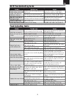
Page 11: ...attery damaged Replace flight battery and follow flight battery instructions Flight conditions may be too cold Make sure battery is warm before use Battery capacity too low for flight conditions Replace battery or use a larger capacity battery LED on receiver flashes and aircraft will not bind to transmitter during binding Transmitter too near aircraft during binding process Power off transmitter m...

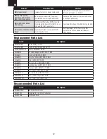
Page 12: ...is set above 100 overdriving the servo Set Travel adjust to 100 or less and or set sub trims to zero and adjust linkages mechanically Replacement Parts List Recommended Parts List Part Description EFLDF180M1 Rotor Delta V 180m EFLDF180M2 Delta V 180m 28mm EDF Unit V2 EFLM30180MDFE Motor UMX MiG 15 BNF EFLU1646 PushrodLinkageSet UMX MiG 15 BNF EFLU1647 Gun Set UMX MiG 15 BNF EFLU6052 Fuse Set w Acc...

Page 13: ...vent that you may need any assistance For questions or assistance please visit our website at www horizonhobby com submit a Product Support Inquiry or call the toll free telephone number referenced in the Warranty and Service Contact Information section to speak with a Product Support representative Inspection or Services If this Product needs to be inspected or serviced and is compliant in the co...

Page 14: ...nd to be compliant with the applicable regulations governing a radio transmitter in the 2 400GHz to 2 4835GHz frequency range Supplier s Declaration of Conformity UMX Mig 15 BNF Basic SAFE EFLU6050 This device complies with part 15 of the FCC Rules Operation is subject to the following two conditions 1 This device may not cause harmful interference and 2 this device must accept any interference re...

Page 15: ...that it is recycled in a manner that protects human health and the environment For more information about where you can drop off your waste equipment for recycling please contact your local city office your household waste disposal service or where you purchased the product EU Compliance Statement UMX Mig 15 BNF Basic SAFE EFLU6050 Horizon Hobby LLC hereby declares that this product is in complianc...

Page 16: ...by logo are trademarks or registered trademarks of Horizon Hobby LLC The Spektrum trademark is used with permission of Bachmann Industries Inc All other trademarks service marks and logos are property of their respective owners US 9 056 667 US 7 898 130 D578 146 PRC ZL 200720069025 PRC ZL 2007001249 www horizonhobby com Created 10 18 59092 EFLU6050 ...

Reviews: