65
Installation
Open
Close
Open
Open
Close
Close
5-6
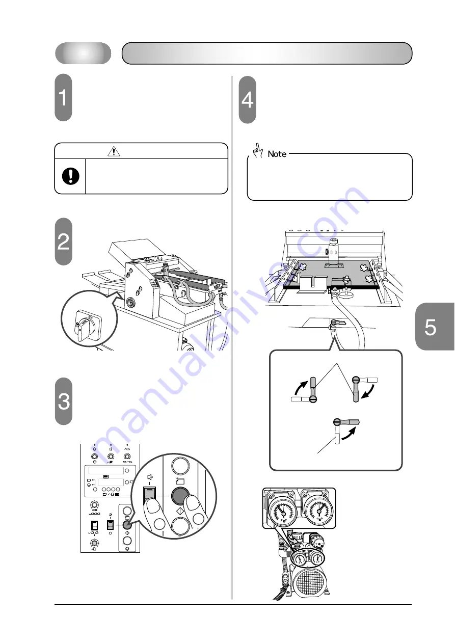
Checking the Pump Rotation Direction
1
0
6
2
3
4
5
1
S
L
5
2
3
4
1
S
L
5
2
3
4
1
S
L
5
2
3
4
1
0
6
2
3
4
5
123
123
C
1
2
Power Switch
Checking the Pump Rotation Direction
(Pump and blower
for 115 V shown)
PRESSURE
0
1
0
0.5
20
20
20
40
40
40
60
60
80
80
100
kPa
kPa
cmHg
kgf/cm
2
100
60
76
0
1
0
0.5
20
20
20
40
40
40
60
60
80
80
100
kPa
kPa
cmHg
kgf/cm
2
100
60
76
Pressure Gauge
Vacuum Gauge
Side Blower Air Valves
Rear Blower Air Valve
If the unit has a pump designed for
115V, check the vacuum and air pres-
sure.
Pressure gauge: 40 kpa
Vacuum gauge: 30 kpa
Close the two side blower air valves and the rear
blower air valve before adjusting the air pressure using
the two regulators. If all the valves are open, there is
no air pressure applied.
If the unit has a pump designed for 230V, it is
not necessary to adjust the air pressure.
Plug the power cable into an outlet.
WARNING
Do not connect too many cables to one
outlet. This can cause a fire or an the
electric shock.
Turn on the power switch.
Turn on the blower and pump.
1) Press the Roller/Feed Start button on the
control panel.
2) Select the Continuous position on the pump
switch.


