33
For more information visit:
www.hornby.com
32
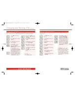
Step 3: RailCom
®
See pages 24 and 38 for further explanation of RailCom
®
8.
Screen will now show as a default
“
RailCom Disable
”.
9.
Rotate
Control 1
until screen
shows “
RailCom Enable
”.
Please Note:
If the decoder used is RailCom
®
equipped then press
Control 1
to
confirm. If not rotate
Control 1
until
“
RailCom Disable
” is displayed and
press
Control 1
to confirm.
Step 5: Short / Extended Addresses
Step 4: Speed Curve Settings
See page 36 for further details on adjusting the speed curve
10.
Having pressed
Control 1
to
confirm the screen will now show
“
SP. Table CV#2#5#6
”. Rotate
Control 1
until screen shows
“
SP. Table CV#67–94
”.
Please Note:
CV#2 #5 #6:
Some decoders use CV2,
CV5 and CV6 as speed curve.
CV#67 – 94:
Some decoders use CV67
– CV94 as speed curve. Check the
information provided with your decoder
for the appropriate CV numbers.
Choose the correct setting and press
Control 1
to confirm.
RailCom
®
is a registered trade mark of Lenz Systems.
Step 6: Decoder Type
12.
Having pressed
Control 1
to
confirm the screen shows
“
Decoder Multi
”.
13.
Rotate
Control 1
until “
Decoder
Acc
” is shown.
Please Note:
“
Decoder Multi
” – specific to
locomotives.
“
Decoder Acc
” – specific to
accessory decoders.
14.
For this example choose “
Decoder
Multi
” and press
Control 1
. The
red LED will flash five times and the
screen will show “
Config
”.
15.
Press
Menu
to return to the main
screen.
Please Note:
Should you use
Operate
mode
the LED will not flash.
11.
Having pressed
Control 1
to
confirm the screen shows “
Address
Short
”. Rotate
Control 1
until
screen shows“
Address Extended
”.
Please Note:
A Short Addressed locomotive uses
CV1 as addresses from 1 – 127. An
Extended Addressed locomotive uses
CV17 & CV18 as addresses from 128
– 9999. Check the information supplied
with the decoder for the correct
setting. Choose the correct setting
and press
Control 1
to confirm.
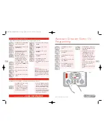
Start Up Voltage Programming (CV)
1.
Press
Menu
. Screen shows
“
Loco
”.
2.
Press
Control 1
. Screen shows
“
Direct
”.
3.
Press
Control 1
. Screen shows
“
Address
”.
4.
Rotate
Control 1
until “
Start V
”
is shown.
5.
Press
Control 1
. Screen shows
“
Start V 000
”.
6.
Either rotate
Control 1
until the
required number is displayed or
using the keypad type in the
required level, e.g. 10. Screen shows
“
Start V 010
”.
7.
Press
Control 1
. Red LED will flash
five times. Screen shows “
Start V
”.
Alternatively the Start Up Voltage may be adjusted using the
Operate Mode
while the locomotive
is on the main line. It must be noted that once the Start Up figure has been input and
Control 1
is
pressed to confirm the red LED will not flash.
Not all electric motors have the same start up voltage requirements.This means that some Digital locomotives
may require their decoders to be adjusted to compensate for the type of motor used. The Hornby Elite has
therefore been designed to provide the facility for the adjustment of the Start Up voltage which can be programmed
into the decoder in up to 255 steps. The lower the number, the lower the start up voltage, however several
attempts to find the optimum Start Up voltage maybe required. Locomotive 1 will be used in this example.
Place the locomotive on the Programming Track.
Elite HBook updated 6.3.07_Q6.qxd 13/3/07 13:09 Page 30


