background image

14

LONGHORN 12V  INSTRUCTION MANUAL

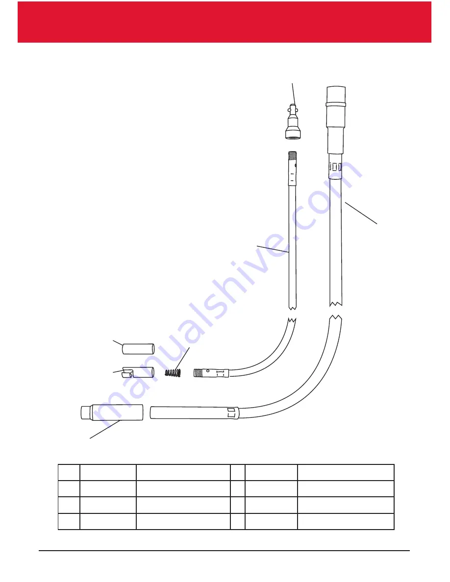
FLEXI DRIVESHAFT

7

5

6

4

2

3

1

1

H11-507

Outer 

4

H18-020 Bayonet Spring

2A H11-505 Inner (Pin)

5 H49-100 Bayonet End

2B H11-506 Inner (Worm)

6 H49-102 Worm End

3

H11-039 Male Coupling

7 H49-002 Flexi Ferule

Summary of Contents for Longhorn 3.2

Page 1: ......

Page 2: ...ng diagram 11 Motor parts list 12 Motor technical drawing 13 Flexible driveshaft technical drawing 14 Solid driveshaft technical drawing 15 Technical data 16 Introduction These instructions must be read by any person intending to use or service the machine Purpose of use This equipment is expressly designed and intended for use for the shearing of sheep goats and animals of the Camelidae family Th...

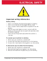
Page 3: ...he battery as these could cause a spark and possibly make the battery explode Don t remove the power leads while the machine is running To connect your machine to a battery 1 Make sure your machine is switched off 2 Connect the red lead to the positive on the battery 3 Connect the black lead to the negative on the battery To disconnect your machine from the battery 1 Make sure your machine is swit...

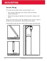
Page 4: ...x and avoids electrical hazards Allows the spring to operate correctly when using a solid drive Mount the machine so that the flexible drive is 20mm clear of the floor or for solid drives 10mm clear of the floor Driveshafts should be set at least 400mm away from the wall 400mm Minimum Secure fixing 10mm Solid Drive 20mm Flexi Drive ...

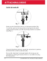
Page 5: ...base casting of the machine until the top fitting reaches it shoulder stop Fig 2 Close the EasyDrive clamp to secure the outer drive in position the inner drive connects automatically Be sure the outer driveshaft is clamped tightly the clamp can be adjusted by screwing the clamp lever in or out before closing the clamp lever Fig 1 Fig 2 Flexible driveshaft ...

Page 6: ...to the base casting of the machine until the top fitting reaches it shoulder stop Fig 2 Close the EasyDrive clamp to secure the outer drive in position the inner drive connects automatically Be sure the driveshaft is clamped tightly the clamp can be adjusted by screwing the clamp lever in or out before closing the clamp lever Fig 1 Fig 2 Solid driveshaft ...

Page 7: ...veshaft Make sure the machine is turned off Push the handpiece onto the drive firmly Rotate clockwise once you feel the handpiece locate into the bayonet rotate another full time For worm drive machines Make sure the machine is turned off Push the handpiece onto the driveshaft firmly Rotate clockwise L O N G H O 1 2 ...

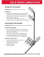
Page 8: ...the machine Greasing the driveshaft Frequency After every 40 hours of use or annually Directions Remove the handpiece and the driveshaft Unscrew the top EasyDrive male fitting Unscrew the bottom bayonet fitting Pull the inner drive from the top of the outer drive Grease inner whilst feeding back into the outer Re fit the bayonet end Re fit the EasyDrive male fitting Attach driveshaft to the machin...

Page 9: ... After every 40 hours of use or annually Directions long gut Unscrew the ferule from the solid elbow Unhook the long gut from the eye spindle Remove the long gut Refit the long gut whilst applying grease Hook the long gut onto the eye spindle Screw the ferule back onto solid elbow Directions short gut Slacken the clamp on short tube Remove the short tube Grease the short gut Refit short tube Tight...

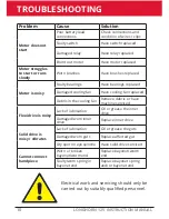
Page 10: ...g fan Have cooling fan replaced Debris in the cooling fan Remove debris or have machine serviced Flexi drive is noisy Lack of lubrication Oil or grease the inner drive Damaged worn inner drive Replace inner drive Solid drive is noisy vibrates Lack of lubrication Oil or grease the guts Damaged worn guts Replace affected gut Dry spot on eye spindle Have solid drive serviced Cannot connect handpiece ...

Page 11: ...11 LONGHORN 12V INSTRUCTION MANUAL WIRING DIAGRAM M 30 85 87 86 DIODE PULL SWITCH RELAY TERMINAL BLOCK ...

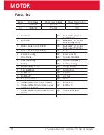
Page 12: ...Clip Red 8 Switch Mounting 24 Crocodile Clip Black 9 Switch 25 EasyDrive Casting 10 Relay 30 amp 12 volt 26 Spring Pull Cord 11 Terminal Block 27 Pull Cord Rod 12 Bolt M5x12 28 Pull Cord 13 Bolt M5x20 29 Lock Nut 14 Shake Proof Washer 30 Gland 15 Insulated Wire Relay to Brush 4mm 31 Bolt M5x20 16 Insulated Wire Terminal Block to relay with Diode 1 5mm 32 Bolt M5x12 17 Insulated Wire Terminal Block...

Page 13: ...13 LONGHORN 12V INSTRUCTION MANUAL MOTOR ...

Page 14: ...STRUCTION MANUAL FLEXI DRIVESHAFT 7 5 6 4 2 3 1 1 H11 507 Outer 4 H18 020 Bayonet Spring 2A H11 505 Inner Pin 5 H49 100 Bayonet End 2B H11 506 Inner Worm 6 H49 102 Worm End 3 H11 039 Male Coupling 7 H49 002 Flexi Ferule ...

Page 15: ...8 005 Spring 5 H18 006 Long Tube 6 H18 007 Ferule 7 H18 008 Eye Spindle 8 H18 009 Elbow Joint 9 H18 010 Solid Cog 10 H18 011 Elbow Guard 11 H18 012 Joint Cap 12 H18 013 Joint Spring 13 H18 014 Short Lug Bolt 14 H18 015 Short Tube 15 H18 016 Short Gut Pin 16 H18 017 Shot Gut Worm 17 H18 018 Long Gut EasyDrive 18 H49 101 Gut Hook 19 H49 100 Bayonet End 20 H49 102 Worm End 21 H11 039 EasyDrive Male C...

Page 16: ...Manufactured by Horner Shearing Lane Side West Bradford Clitheroe BB7 4QH United Kingdom ...

Reviews: