background image

WCM802/900


20


JUN


2005


PAGE


9


Pin Signals 

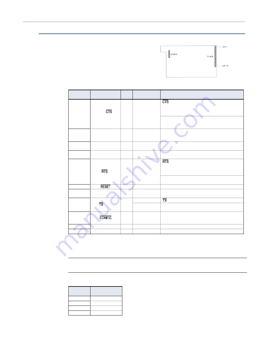
Figure


1.1.


WCM802


/


WCM900


OEM


RF


Module


Pin


Numbers


(bottom


view,


pins


protruding)


Table


1.2.


J1


Pin


Signal


Descriptions


(Low

asserted


signals


distinguished


with


a


horizontal


line


over


signal


name.)


Module 

Pin 

Signal Name 

I/O 

When Active 

Function 

 (clear-to-send) flow control – When pin is driven low, 

UART host is permitted to send serial data to the module.  

Refer to the Serial Communications [p9] and CS Command 

[p19] sections for more information. 

DO2 / 

 /  

RS-485 Enable 

O* low 

RS-485 Enable – To configure this pin to enable RS-485 (2-

wire or 4-wire) communications, refer to the Serial 

Communications [p9] and CS Command [p19] sections. 

DI3 / SLEEP 

I* 

high 

By default, DI3 pin is not used. To configure this pin to 

support Sleep Modes, refer to the Sleep Mode [p13], SM 

Command [p27] and PW Command [p24] sections. 

DO (data out) 

O* 

n/a 

Serial data exiting the module (to the UART host). Refer to 

the Serial Communications [p9] section for more information. 

DI (data in) 

n/a 

Serial data entering the module (from UART host). Refer to 

the Serial Communications [p9] section for more information. 

 (request-to-send) flow control – By default, this pin is not 

used. To configure this pin to regulate the flow of serial data 

exiting the module, refer to the Serial Communications [p9] 

and RT Command [p26] sections. 

5 DI2 

 / CMD 

I** 

low 

CMD –Refer to Binary Commands [p15] and RT Command 

[p26] sections to enable binary command programming. 

 I*  low Re-boot 

module. 

DO3 / RX LED 

high 

Pin is driven high during RF data reception; otherwise, the 

pin is driven low. Refer to the CD Command [p19] to enable. 

low 

 - Pin pulses low during RF transmission. 

 / PWR 

high 

PWR – Indicates power is on and module is not in Sleep 

Mode. 

 I***  low 

Pin can be used as a backup method for entering Command 

Mode during power-up. Primary method is with “+++”. Refer 

to the Command Mode [p14] section for more information.  

10 

VCC 

5 VDC regulated (± 0.25) 

11 GND 

Ground 


*


Module


has


10K

 Ω 

internal


pull

up


resistor


**


Module


has


10K

 Ω 

internal


pull

down


resistor


***


Module


has


100K

 Ω 

internal


pull

up


resistor


Note:  When integrating the WCM802 / WCM900 Module with a Host PC Board, all lines that are not 
used should be left disconnected (floating). 


Table


1.3.


J2


Pin


Signal


Descriptions


Module 

Pin 

Signal Name 

1 reserved 
2 GND 
3 GND 
4 GND 


J2


Pins


are


used


primarily


for


mechanical


stability


and


may


be


left


disconnected.


Summary of Contents for HE-WCM802

Page 1: ...Supplement for HE800WCM802 and HE800WCM900 HE WCM802 and HE WCM900 Denotes Plastic Models SmartStack Wireless Communication OEM RF Modem 20 June 2005 MAN0789 01 ...

Page 2: ...PAGE 2 20 JUN 2005 WCM802 900 ...

Page 3: ... otherwise without the prior agreement and written permission of Horner APG Inc Copyrights of part of this manual belong to MaxStream Inc All software described in this document or media is also copyrighted material subject to the terms and conditions of the Horner Software License Agreement Information in this document is subject to change without notice and does not represent a commitment on the...

Page 4: ...IGINALLY INSTALLED THIS WARRANTY SHALL APPLY ONLY WITHIN THE BOUNDARIES OF THE CONTINENTAL UNITED STATES In no event whether as a result of breach of contract warranty tort including negligence or otherwise shall HE APG or its suppliers be liable of any special consequential incidental or penal damages including but not limited to loss of profit or revenues loss of use of the products or any assoc...

Page 5: ...nsmit Mode 14 Receive Mode 16 Sleep Mode 16 Command Mode 17 3 Advanced Programming 19 Programming the Module 19 AT Command Example 19 Binary Command Example 19 Command Descriptions Short 20 Command Descriptions Long 21 Appendix A Agency Certifications 34 FCC Certification 34 OEM Labeling Requirements 35 Antenna Usage 35 FCC Approved Antennas 36 European Compliance 2 4 GHz only 37 OEM Labeling Requ...

Page 6: ...PAGE 6 20 JUN 2005 WCM802 900 NOTES ...

Page 7: ...or line of sight up to 3 miles 5 km w 2 1 dBm dipole antenna Outdoor line of sight up to 10 miles 16 km w high gain antenna Receiver Sensitivity 110 dBm 900 MHz 105 dBm 2 4 GHz Advanced Networking Security True peer to peer no master required point to point point to multipoint multidrop Retries and Acknowledgements 7 hopping channels each with over 65 000 available network addresses FHSS Frequency...

Page 8: ...102 dBm General Frequency Range 902 928 MHz 2 4000 2 4835 GHz Spread Spectrum Frequency Hopping Wide band FM modulator Network Topology Peer to Peer Point to Multipoint Point to Point Multidrop Channel Capacity 7 hop sequences share 25 frequencies Serial Data Interface CMOS UART Power Requirements Supply Voltage 5 VDC 0 25 V regulated Transmit Current 150 mA Receive Current 50 mA Power Down Curren...

Page 9: ...ction for more information request to send flow control By default this pin is not used To configure this pin to regulate the flow of serial data exiting the module refer to the Serial Communications p9 and RT Command p26 sections 5 DI2 CMD I low CMD Refer to Binary Commands p15 and RT Command p26 sections to enable binary command programming 6 I low Re boot module 7 DO3 RX LED O high Pin is drive...

Page 10: ...cations A and B refer to Figure 1 2 Table 1 4 AC Characteristics SY parameter 0 symbols correspond to Figure 1 2 and Figure 1 3 Symbol Description 19200 baud rate 32 byte packet 19200 timing B number of bytes 9600 baud rate 32 byte packet 9600 timing B number of bytes TTX Latency from the time data is transmitted until received 54 0 ms For 0 B 64 T 41 6 0 4 B ms For B 63 T 66 8 ms 72 0 ms For 0 B ...

Page 11: ...Output Low Voltage IOL 20 mA Vcc 5V 0 7 0 5 V VOH Output High Voltage IOH 20 mA Vcc 5V 4 0 2 0 V IIL Input Leakage Current I O Pin Vcc 5 5V pin low absolute value 3 µA IIH Input Leakage Current I O Pin Vcc 5 5V pin high absolute value 3 µA IIL2 DO Vcc VI 10 mA IIL3 CONFIG Vcc VI 47 mA IIH2 Vcc VI 10 mA Reset pulse must last at least 250 nanoseconds VI the input voltage on the pin Mechanical Drawin...

Page 12: ...ontal line over signal name Serial Data Data enters the prName Module through the DI pin pin 4 as an asynchronous serial signal The signal should idle high when no data is being transmitted The UART performs tasks such as timing and parity checking that are needed for data communications Serial communication consists of two UARTs configured with compatible parameters baud rate parity start bits st...

Page 13: ...etwork any serial data that arrives on the DI pin Pin 4 is placed in the DI Buffer The data in the DI buffer will be transmitted over the air when the module no longer detects RF data in the network Hardware Flow Control When the DI buffer is 17 bytes away from being full by default the module de asserts high to signal to the host device to stop sending data refer to FT Flow Control Threshold and ...

Page 14: ...nd initiate an RF connection with other modules Figure 2 5 Transmission of Data Æ Once in Transmit Mode the module initializes a communications channel Channel initialization is the process of sending an RF initializer that synchronizes receiving modules with the transmitting module When streaming multiple RF packets the RF Initializer is only sent in front of the first packet During channel initi...

Page 15: ...te modules from Sleep Mode Refer to the FH LH HT and SM Commands for more information The length of the wake up initializer should be longer than the length of time remote modules are in cyclic sleep Header The header contains network addressing information that filters incoming RF data The receiving module checks for matching a VID Hopping Channel and Destination Address Data that does not pass t...

Page 16: ...ed only for Pin Sleep option In Sleep Mode the module will not transmit or receive data until the module first transitions to Idle Mode All Sleep Modes are enabled and disabled using SM Command Transitions into and out of Sleep Modes are triggered by various events as shown in the table below Table 2 1 Summary of Sleep Mode Configurations Sleep Mode Setting Transition into Sleep Mode Transition ou...

Page 17: ...No characters sent for one second see BT Guard Time Before Command Input three plus characters within one second see CC Command Sequence Character Command No characters sent for one second see AT Guard Time After Command To Send AT Commands Send AT commands and parameters using the syntax shown below Figure 2 9 Syntax for sending AT Commands NOTE To read a parameter value stored in a register leav...

Page 18: ...k in the received data before executing the command The signal will frame the response coming from the binary command request see graphic below CMD pin 5 must be asserted in order to send binary commands to an WCM802 WCM900 Module CMD can be asserted to recognize commands anytime during transmission or reception of data A minimum time delay of 100 µs after the stop bit of the command byte has been...

Page 19: ...rminal tab to send data to the module the PC com port settings must match the following module parameter values baud parity stop bits Use the PC Settings tab to configure PC com port settings to match module parameter values Refer to BD Baud Rate and NB Parity Commands for module parameter values Binary Command Example To Send Binary Commands Example Use binary commands to change the WCM802 WCM900...

Page 20: ...p Initializer 0 0xFFFF x 100 msec Sleep Low Power 2 0xFFFF ID v 4 2B 0x27 39d Module VID User settable 0x10 0x7FFF Read only 0x8000 0xFFFF Networking 2 LH 0x0C 12d Wake up Initializer Timer 0 0xFF x 100 msec Sleep Low Power 1 1 MK 0x12 18d Address Mask 0 0xFFFF Networking 2 0xFFFF NB v 4 27B 0x23 35d Parity 0 4 Serial Interfacing 1 0 PC v 4 22 0x1E 30d Power up Mode 0 1 Command Mode Options 1 0 PW...

Page 21: ...ed by the BD Command Note If the serial data rate is set to exceed the fixed RF data rate of the WCM802 WCM900 module flow control may need to be implemented as described in the Pin Signals and Flow Control sections of this manual BT Guard Time Before Command Command Mode Options BT Command is used to set the DI pin silence time that must precede the command sequence character CC Command of the AT...

Page 22: ...d is used to select the behavior of the DO2 pin signal This output can provide RS 232 flow control control the TX enable signal for RS 485 or RS 422 operations or set the default level for the I O line passing function By default DO2 provides RS 232 Clear to Send flow control AT Command ATCC Binary Command 0x13 19 decimal Parameter Range 0x20 0x7F Default Parameter Value 0x2B ASCII sign Number of ...

Page 23: ...k to the terminal when ATE1 is active E0 is the default ER Receive Error Count Command Diagnostics Set Read the receive error The error count records the number of packets partially received then aborted on a reception error This value returns to 0 after a reset and is not non volatile Value does not persist in the module s memory after a power up sequence Once the Receive Error Count reaches its ...

Page 24: ...HP Hopping Channel Command Networking HP Command is used to set the module s hopping channel number A channel is one of three layers of addressing available to the WCM802 WCM900 module In order for modules to communicate with each other the modules must have the same channel number since each network uses a different hopping sequence Different channels can be used to prevent modules in one network...

Page 25: ... matching VIDs will not receive unintended data transmission LH Wake up Initializer Timer Command Sleep Low Power LH Command adjusts the duration of time for which the RF initializer is sent When receiving modules are put into Cyclic Sleep Mode they power down after a period of inactivity specified by ST Time before Sleep Command and will periodically awaken and listen for transmitted data In orde...

Page 26: ... on If PC Command is enabled with SM Parameter set to 1 DI3 pin 2 can be used to enter the module into AT Command Mode When the DI3 pin is de asserted low the module will wake up in AT Command Mode This behavior allows module DTR emulation AT Command ATMK Binary Command 0x12 18 decimal Parameter Range 0 0xFFFF Default Parameter Value 0xFFFF Destination address DT parameter of the transmitting modu...

Page 27: ... attempting to resend a packet If the transmitter fails to receive an acknowledgement after sending a packet it will insert a random number of delay slots ranging from 0 to RN minus 1 before attempting to resend the packet Each delay slot lasts for a period of 38ms If two modules attempted to transmit at the same time the random time delay after packet failure would allow one of the two modules to...

Page 28: ...ived With a non zero RP parameter the Config pin will be an input for RP ms after power up RR Retries Command Networking RR Command specifies the number of retries that can be sent for a given RF packet Once RR Command is enabled set to a non zero value RF packet acknowledgements and retries are enabled After transmitting a packet the transmitter will wait to receive an acknowledgement from a rece...

Page 29: ...er Range 0 2 Parameter Value Configuration 0 disabled 1 Enable Binary Programming 2 Enable Flow Control Default Parameter Value 0 Number of bytes returned 1 AT Command ATSB Binary Command 0x36 54 decimal Parameter Range 0 1 Parameter Value Configuration 0 1 stop bits 1 2 stop bits Default Parameter Value 0 Number of bytes returned 1 Minimum Firmware Version Required 4 2B AT Command ATSH Binary Com...

Page 30: ...ial Port Sleep SM 2 Serial Port Sleep is a Sleep Mode in which the WCM802 WCM900 Module runs in a low power state until serial data is detected on the DI pin When Serial Port Sleep is enabled the module goes into Sleep Mode after a user defined period of inactivity no transmitting or receiving of data This period of time is determined by ST Time before Sleep Command Once a character is received th...

Page 31: ... interval time defined by SM Sleep Mode Command must be shorter than the interval time defined by LH Wake up Initializer Timer For example If SM 4 Cyclic 1 0 second sleep the LH Parameter should equal 0x0B 1 1 seconds With these parameters set there is no risk of the receiving module being asleep for the duration of wake up initializer transmission Cyclic Scanning explains in further detail the re...

Page 32: ...ameter to 0x14 20 decimal allows all modules to remain in sync for 2 seconds after the last data packet was received Synchronization information is not re sent unless transmission stops for more than 2 seconds This command allows significant savings in packet transmission time Warning Not recommended for use in an interference prone environment Interference can break up the session and the communi...

Page 33: ...mware Version of the WCM802 WCM900 Module WR Write Command Special WR Command writes configurable parameters to the module s non volatile memory Parameter values remain in the module s memory until overwritten by future use of WR Command If changes are made without writing them to non volatile memory the module reverts back to previously saved parameters the next time the module is powered on AT C...

Page 34: ...5 109 before declaring compliance of their final product to Part 15 of the FCC Rules IMPORTANT The WCM802 WCM900 OEM RF Modules have been certified for remote and base radio applications If the WCM802 WCM900 will be used for portable applications the device must undergo SAR testing This equipment has been tested and found to comply with the limits for a Class B digital device pursuant to Part 15 o...

Page 35: ...ntennas not listed in the tables must be tested to comply with FCC Section 15 203 unique antenna connectors and Section 15 247 emissions RF Exposure WARNING This equipment is approved only for mobile and base station transmitting devices separation distances of i 20 centimeters or more for antennas with gains 6 dBi or ii 2 meters or more for antennas with gains 6 dBi should be maintained between t...

Page 36: ... Min Separation Distance Yagi 6 dBi Fixed 2 m Yagi 8 8 dBi Fixed 2 m Yagi 9 dBi Fixed 2 m Yagi 10 dBi Fixed 2 m Yagi 11 dBi Fixed 2 m Yagi 12 dBi Fixed 2 m Yagi 12 5 dBi Fixed 2 m Yagi 13 5 dBi Fixed 2 m Yagi 15 dBi Fixed 2 m Omni Direct 2 1 dBi Fixed Mobile 20 cm Omni Direct 3 dBi Fixed Mobile 20 cm Omni Direct 5 dBi Fixed Mobile 20 cm Omni Direct 7 2 dBi Fixed 2 m Omni Direct 8 dBi Fixed 2 m Omn...

Page 37: ... nature of the apparatus The CE marking must be affixed visibly legibly and indelibly Furthermore since the usage of the 2400 2483 5 MHz band is not harmonized throughout Europe the Restriction sign must be placed to the right of the CE marking as shown below See the R TTE Directive Article 12 and Annex VII for more information Figure A 4 CE Label Required on OEM Equipment Restrictions France Fran...

Page 38: ...r Type Gain Application Min Separation Distance A24 HABMM P6I Dipole 2 1 dBi Fixed Mobile 20cm A24 HBMM P6I Dipole 2 1 dBi Fixed Mobile 20cm A24 HABSM Dipole 2 1 dBi Fixed Mobile 20cm A24 QABMM P6I Monopole 1 9 dBi Fixed Mobile 20cm A24 QBMM P6I Monopole 1 9 dBi Fixed Mobile 20cm A24 Q1 Monopole 1 9 dBi Fixed Mobile 20cm Can be approved for portable applications if integrator gains approval throug...

Page 39: ...JUN 2005 PAGE 39 Appendix B Additional Information Technical Support For user manual updates and assistance contact Technical Support North America 317 916 4274 www heapg com Europe 353 21 4321 266 www horner apg com ...

Page 40: ...PAGE 40 20 JUN 2005 WCM802 900 NOTES ...

Reviews: