MAN0508-03
08 JUN 2005
PAGE 3
b. DIN-Rail
Mounting
1.
Read the Installation Chapter in the hardware manual of the controller you are using prior to
mounting the FOX104 / FOX404. Observe requirements for the panel layout design and
adequate clearances. A checklist is provided for your convenience in the hardware manual. (See
the
Additional References
section in this document.)
2.
Determine length of DIN-Rail needed. (Refer to Figure 2.)
3.
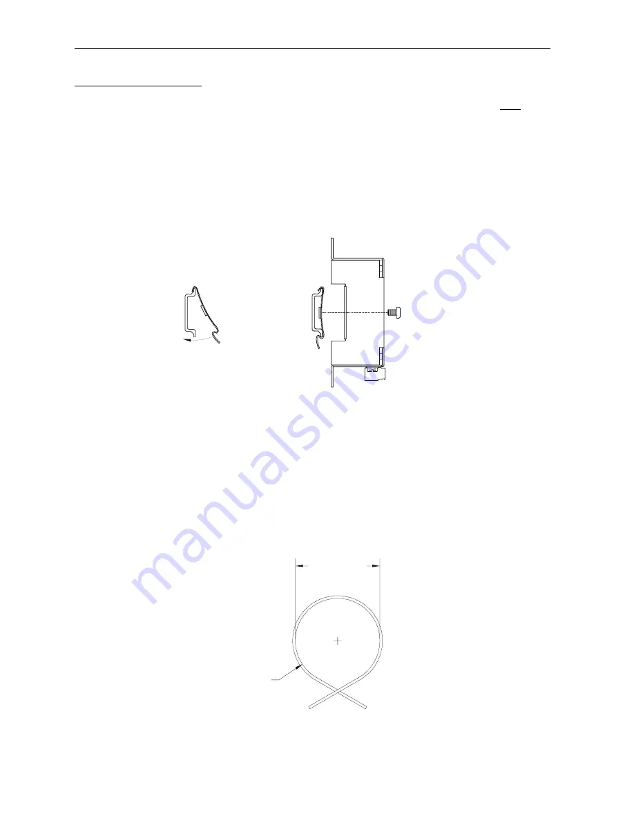
Noting the proper location, attach two (2) DIN-Rail mounting clips (included with FOX unit) to the
DIN-Rail by hooking the clips over the top of the Rail and rocking down and snapping over the
bottom of the Rail. (Refer to Figure 3.)
4.
Adjust clips as necessary by sliding them along the DIN-Rail to align with the holes in the tabs of
the FOX unit. Using the provided screws, mount the Fox unit to the clips. Tighten screws as
necessary to hold the unit securely. (Refer to Figure 3.)
Figure 3 – (Left) DIN-Rail and Mounting Clips, and (Right) FOX104 / FOX404 DIN-Rail Mounting
2.4
Fiber Optic Cable Installation
Important considerations for installing the FOX include the following guidelines:
a.
To ensure reliable communication between the FOX base and OCS/RCS module, high quality
cables need to be installed. See Table 2 for fiber cable part numbers.
b.
The maximum fiber optic cable distance is 10 meters between drops.
c.
During installment of the fiber optic cable, all direction changes need to adhere to a
Minimum
Bend Radius
of one inch (25.44mm).
Figure 3 – Fiber Optic Cable Bend Radius
1.00” (25.4mm) Min.
Bend Radius
001FOX011
2.00” (50.8mm)
Min. Diameter
001FOX012
Close-up of mounting clips
being hooked on to DIN-rail.
DIN-Rail
Mounting
Clips
FOX104 /
FOX404


