background image

15


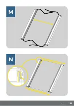
De trekbalk van de blackout cassette is nu opgespannen, 


omdat de koorden in de hoekstukken van de mesh cassette bij 


de blackout trekbalk horen. Controleer of deze trekbalk recht 


zit ten opzichte van de cassette, of deze soepel loopt en of 


deze niet zakt als de UCS rechtop gezet wordt en de blackout 


uitgetrokken wordt. 


Indien de trekbalk scheef staat, is het koord in een van de 


hoekstukken strakker aangetrokken dan de andere. Indien 


de trekbalk niet soepel loopt zijn de koorden mogelijk te 


strak aangespannen. Indien de trekbalk zakt als het blackout 


wordt uitgetrokken zijn de koorden niet voldoende 


aangetrokken. Om het systeem perfect op te spannen moet er 


gespeeld worden met de spanning op de koorden.


Herhaal voorgaande stappen om de trekbalk van het mesh op 


de juiste spanning te zetten.

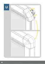
5.4 Installatie (pag. 26 (R) t/m pag. 28 (U))

Nadat het product geassembleerd is kan deze op de wand worden 

geïnstalleerd. Volg voor het installeren van dit product stap R t/m U.

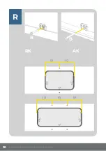
R: 

Indien het product breder is dan 900 mm. zijn er Z-clips 


meegeleverd. Monteer deze Z-clips op de juiste afstand van 


het raamgat. Bij RK moet de Z-clip direct tegen het rubber aan 


worden geplaatst en bij PV moet het Z-profieltje op de rand 


van het raamgat worden geplaatst. Verdeel de Z-clips 


evenredig over beide horizontale zijdes. Schroef de Z-profieltjes 


vast met schroef B.

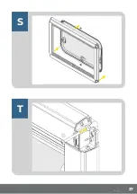
S: 

Plaats het product, met de blackout cassette aan de  


onderkant, tegen de wand. Indien de Z-clips gebruikt zijn zorg 


er dan voor dat de profielen goed om de Z-clips heen vallen. 


Als er geen Z-clips gebruikt zijn, lijn het product dan netjes uit 


op het raam.

Let op! 

Als de bijgeleverde schroeven niet vastgrijpen in de 

muur moet u muurpluggen gebruiken. Let hierbij op 

dat u niet door de muur heen boort.

Summary of Contents for Resizeable UCS

Page 1: ...Montagehandleiding Resizeable UCS Installation Manual...

Page 2: ...4 HORREX MONTAGEHANDLEIDING...

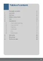
Page 3: ...ns 8 3 Safety instructions 9 4 Use 10 5 Installation 11 5 1 Check before installing 11 5 2 Customization 11 5 3 Assembly 14 5 4 Installation 15 5 5 Use 16 5 6 Maintenance 16 6 Warranty 29 7 Recycling...

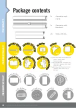
Page 4: ...C A P C ORNER C A P Systems smaller than 900 mm have 4 wall screws and no Z clips Systems between the 900 and 1400mm have 6 wall screws and 2 Z clips Systems wider than 1400 mm have 8 wall screws and...

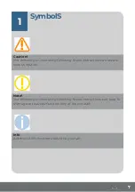
Page 5: ...y following these instruction can lead to serious injuries Note Not following or incorrectly following these instructions can lead to damage or reduced functionality of the product Info Additional inf...

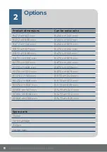
Page 6: ...B 473 x H 502 mm B 872 x H 1100 mm B 473 x H 809 mm B 1172 x H 501 mm B 873 x H 240 mm B 1172 x H 808 mm B 873 x H 502 mm B 1172 x H 1100 mm B 873 x H 809 mm B 1472 x H 501 mm B 1173 x H 240 mm B 147...

Page 7: ...fications to the product without the permission of the producer Use for purposes other than described in the manual Check before installing whether the dimensions of the product match with where the p...

Page 8: ...l thickness of 26 mm so that the screws do not portrude on the out side of the wall Use only in combination with the supplied parts or additional parts from Horrex This can be found in chapter 2 of th...

Page 9: ...while drilling fastening screws 5 2 Customization pag 17 A t m pag 22 L It is possible to change the dimensions of the product into the desired window size For this measure the height and width of th...

Page 10: ...they have been cut on both sides have the cutting width that has been calculated with help of the table on page 11 Use the following formula to calculate how much should be cut from either side casse...

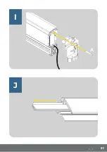
Page 11: ...ween the pull bar and the guide I Fasten a corner cap on both sides of every cassette Use screw A for this J Pull the brushes out of the side profiles K Cut both side profiles to the right size The ri...

Page 12: ...or schroef A P Klik aan de achterzijde van het systeem aan ieder hoekstuk een maan Q Span het systeem op Begin aan de mesh cassette zijde Trek eerst de trekbalk van de blackout zijde volledig naar de...

Page 13: ...juiste spanning te zetten 5 4 Installatie pag 26 R t m pag 28 U Nadat het product geassembleerd is kan deze op de wand worden ge nstalleerd Volg voor het installeren van dit product stap R t m U R In...

Page 14: ...ebruik g n scherpe objecten of chemische schoonmaakmiddelen die het product kunnen beschadigen Info Bij het bevestigen van grotere systemen wordt het aangeraden om een tweede persoon te laten assister...

Page 15: ...17 B A...

Page 16: ...18 HORREX MONTAGEHANDLEIDING C D...

Page 17: ...19 E F...

Page 18: ...20 HORREX MONTAGEHANDLEIDING G H A...

Page 19: ...21 I J A...

Page 20: ...22 HORREX MONTAGEHANDLEIDING K L...

Page 21: ...23 M N...

Page 22: ...24 HORREX MONTAGEHANDLEIDING O P A...

Page 23: ...25 Q...

Page 24: ...26 HORREX MONTAGEHANDLEIDING R RK AK 1 2 1 2 1 3 1 3 1 3 B B...

Page 25: ...27 S T B...

Page 26: ...28 HORREX MONTAGEHANDLEIDING U...

Page 27: ...jke regelgeving Gelieve het product niet weg te doen met het huis tuin en keukenafval Garantie Voor dit product geldt standaard een garantie van 2 jaar Als het product defect is neem dan in eerste ins...

Page 28: ...0 HORREX MONTAGEHANDLEIDING 8 Technische data Onderdeel Materiaal Basisprofiel PVC Kapprofiel PVC Trekbalk Aluminium Overige kunststof onderdelen PA6 PA6 6 Blackout PET met aluminiumlaag Mesh Polyeste...

Page 29: ...31...

Page 30: ...32 HORREX MONTAGEHANDLEIDING...

Page 31: ...33...

Page 32: ...Horrex BV Taanderijstraat 19 3133 ET Vlaardingen TEL 31 0 10 26 19 600 www horrex nl info horrex nl www drivingchangeint com...

Reviews: