background image

HORSCH DrillManager

HORSCH DrillManager

ME

ME

Operating instructions

Art: 80660201 en

Read thoroughly prior to starting up! 

Keep operating instructions in a safe place!

03/2007

Specialist in modern 

cultivation and seeding technology

SW 4.16

Summary of Contents for DrillManager ME

Page 1: ...r HORSCH DrillManager ME ME Operating instructions Art 80660201 en Read thoroughly prior to starting up Keep operating instructions in a safe place 03 2007 Specialist in modern cultivation and seeding technology SW 4 16 ...

Page 2: ......

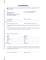
Page 3: ...ranty claims will be accepted if this machine registration form is not returned I am aware that a warranty claim will only be valid if this form has been fully completed signed and returned to HORSCH Maschinen GmbH or has been given to the Service Technician immediately after first instruction Place date of first instruction Buyer s signature Dealer Name Street Postal code Place Tel Fax E mail Cus...

Page 4: ......

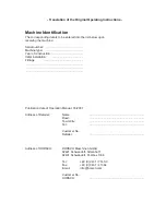
Page 5: ...ial number Machine type Year of construction Initial installation Fittings Publication date of Operation Manual 03 2007 Address of Retailer Name Road Town City Tel Customer No Retailer Address of HORSCH HORSCH Maschinen GmbH 92421 Schwandorf Sitzenhof 1 92401 Schwandorf Postbox 1038 Tel 49 0 9431 7143 0 Fax 49 0 9431 41364 E mail info horsch com Customer No HORSCH ...

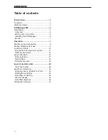
Page 6: ...etting 8 Screen display work mask 9 Function symbols 10 Bout marker and hydraulic control 11 Half side shut down 12 Seed calibration 14 Rotor selection 17 Seed Check 19 Performance data 19 Input of machine data 20 Tram line rhythm 26 Seed flow monitoring 34 Entering sensor numbers for FGS 34 Setting the sensitivity 35 Seed flow monitoring 35 Alarm message 36 Seed flow diagnose 36 Diagnostics progr...

Page 7: ...ting instructions for the purpose of improving the machine or the additional equipment In accordance with its intended purpose the HORSCH DrillManager may only be used to control and monitor seeders and their compo nents and to apply liquid fertiliser Any further usage shall be deemed not be in accordance with its intended purpose Warranty claims Warranty claim forms must be sent through your loca...

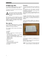
Page 8: ...ve and one liquid fertiliser control hydraulic control for raising wings and track indicator control half side control Sensors for Fan travel speed radar tank empty indicator 2 channels Connection for work signal Off switch Computer All components and sensors are connected to computer and monitor by means of the wiring loom The computer uses a bus system or the ISO bus system to communicate with t...

Page 9: ...tiliser 2 pole Flat plug with diode shut off valve Cable 8 pole automatic tram line control set to Magnet 1 Wings right 2 Wings right 3 Wings left 4 Wings left 5 Pre emergence markers right 6 Pre emergence markers left 7 Ground all 8 Ground all Cable 8 pole automatic tram line control set to Motor 1 Motor right 2 Motor right 3 Motor left 4 Motor left 5 Pre emergence markers right 6 Pre emergence m...

Page 10: ...mm and two 2 5 mm cables for electric power supply For deliveries up until approx May 2006 only the two 6 mm cables must be connected there is only one 50 A fuse installed From around May 2006 all cables must be con nected there is an additional 10 A fuse for the red 2 5 mm cable The monitor should not obstruct the field of vision to the road Installation Basic equipment with monitor Assemble the ...

Page 11: ...ed select the desired number with the and confirm with Re turn The system will automatically change to the next number With the arrow keys the desired cipher can be directly selected If various terms have been predetermined these will also be highlighted with the keys and confirmed with Return Monitor The monitor is plugged on the pre assembled bracket in the tractor and connected to the com puter...

Page 12: ...ay version e g 3 14 The drill program software version is displayed in diagnostics Menu 2 Screen settings for Brightness and Contrast use the membrane keyboard to set accord ingly Menu 3 Set date and time Menu 4 Information about available memory in computer and monitor In case of reprogramming or when replacing the computer delete the monitor memory X by pressing key 5 In case of a restart the pr...

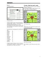
Page 13: ...Danish da Polish pl Czech cs Romanian ro Spanish es Swedish sv Hungarian hu Serbian sr Russian ru Press the system change over key 1 to return to the selection press the key to select the drill program and confirm with Return Screen display work mask After switching on the work mask will always appear as initial page The displayed image will always depend on the setting and the available equipment...

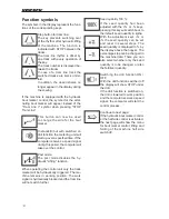
Page 14: ...e post mode disables the hy draulic Lifting function When operating the control unit only the track marker will be hydraulically triggered The ma chine remains in working position The work signal is hydraulically blocked and the tram line will not switch further Seed quantity 100 If the seed quantity had been adjusted with the or keys pressing this key will switch back to the default seed quantity...

Page 15: ...itch the hydraulic valve block over to Fold ing The functions Lifting Lowering and the drill function are switched off Lifting and lowering the machine The function Lifting Lowering is automati cally activated when activating the bout marker function If the bout marker is switched on the first actuation of the key will switch off the bout marker and the second actuation will disable the Lifting Lo...

Page 16: ...the second work page As soon as a key for shutting down a half side is pressed the corresponding half side will flash in the displayed graph until the sensor sends a signal to the computer when end position is reached In end position the closed half side is hidden The seed quantity is reduced by half the seed quantity display in kg ha remains unchanged be cause the working width has also be halved...

Page 17: ...rther functions Available displays The number of the tram line rhythm from the table not the number of bouts The setpoints for seed and fertilizer quanti ties in kg ha or for liquid fertiliser in l ha Hopper 1 filling level indicator for seed and fertiliser hopper Hopper 2 monitoring of bridging in metering unit RPM meter for two shafts Sensitivity setting for seed flow monitoring Display of amoun...

Page 18: ...he seed calibration the setpoints for seed and metering quantities must be entered to enable calculation of the working speed The metering unit must have the correct rotor installed Rotor selection The rotor is dependent on seed quantity working speed and working width of the drill The following tables show the minimum and maximum seed quantities ate various working widths and the available rotor ...

Page 19: ...ration process However the hopper should not be filled completely this applies particularly for fine seeding to enable easier exchange of rotor if it had been incor rectly selected For correct calculation of the seed quantity all cells in the rotor should be filled when starting the seed calibration For this purpose press the key Metering Unit The rotor will rotate as long as specified in the Conf...

Page 20: ...ny seeds that may have remained in the venturi area Weigh the turned off seed Press the Enter key to select Calibration quantity and enter the weight with the and keys After entering the calibration weight the pos sible speed range will be calculated and displayed If the displayed speed range corresponds with your desired drill speed you may start the ferti liser calibration or in case of single h...

Page 21: ...2 17 2 13 40 5 24 200 18 150 12 100 10 80 10 12 100 9 75 6 50 5 40 15 8 67 6 50 4 33 3 27 100 5 60 500 45 375 30 250 24 200 10 30 250 23 188 15 125 12 100 15 20 167 15 125 10 83 8 67 170 5 102 850 77 638 51 425 41 340 10 51 425 38 319 26 213 20 170 15 34 283 26 213 17 142 14 113 250 5 150 1250 113 938 75 625 60 500 10 75 625 56 469 38 313 30 250 15 50 417 38 313 25 208 20 167 320 5 192 1600 144 12...

Page 22: ... 15 2 13 1 11 1 8 1 6 40 5 9 75 8 67 6 50 4 33 10 5 38 4 33 3 25 2 17 15 3 25 3 22 2 17 1 11 100 5 23 188 20 167 15 125 10 83 10 11 94 10 83 8 63 5 42 15 8 63 7 56 5 42 3 28 170 5 38 319 34 283 26 213 17 142 10 19 159 17 142 13 106 9 71 15 13 106 11 94 9 71 6 47 250 5 56 469 50 417 38 313 25 208 10 28 234 25 208 19 156 13 104 15 19 156 17 139 13 104 8 69 320 5 72 600 64 533 48 400 32 267 10 36 300...

Page 23: ...he metering accuracy The same procedure as for seed calibration must be performed for this purpose The computer retrieves the calibration data from the last seed calibration and uses the revolutions of the new seed calibration to calculate a new value for the calibration quantity When switching off the calibration switch it shows this value under Calibration quantity in kg If the same seed is used...

Page 24: ... tered before initial start up of the machine After switching on the first page of the main menu is displayed Use the arrow key to switch to the second page The key for machine data opens a further selection page Specification of seed quantity in kg ha Adjustment value for seed quantity Specification placement quantity solid ferti liser in kg ha or liquid fertiliser in l ha Selection of whether th...

Page 25: ...per only occurs once It must be confirmed with the Escape key The alarm function will only be activated again after the hopper sensor has been covered by seed during filling Bridging B The sensor for bridging monitoring is installed in the metering unit In case of bridging in the seed or fertiliser hopper the metering unit will run empty and no seed or fertiliser will be placed In case of an alarm...

Page 26: ... an ad ditional valve block Folding machine for use with foldable machines Fertiliser control If the machine is equipped with twin hopper or with liquid fertiliser facility the system must here be selected Half side control If a half side control is installed you must select LINAK or WINGS as control depending on the system The LINAK adjustment motor is mounted to the metering unit Tram line syste...

Page 27: ...calibration This menu can be used to run a seed calibration see seed calibration Prime rotor time The rotor rotates as long as speci fied under prime rotor time A setting of 5 seconds is enough to e g place seed in field corners If the computer receives a speed signal dur ing this period the computer will take over the control Calibration factor The calibration factor value for seed and fertiliser...

Page 28: ... calculate the percentage and change the calibra tion factor by the same percentage The deviation is displayed in the menu bar per formance data second work page with key i in the calculated amount in litres to the actually placed quantity If the displayed quantity is lower than the actu ally placed quantity the calibration value must be reduced and vice versa Control factor The control factor inf...

Page 29: ...ey The value will be saved and used for all calculations Configuration 4 This menu page is used to enter the data for speed shaft monitoring and fan For the speed the pulses for the 100 m distance must be entered The entry serves as a calculation information for speed display area calculation and to control the seed and fertiliser quantity The number of pulses can be entered directly approx 9700 F...

Page 30: ... or fallen short of an audible and visible alarm will be emitted Tram line rhythm Overview and selection of tram line rhythm The R No only represents the number from the table and has no relevance for the rhythm The Length shows the number of bouts until the rhythm repeats itself The fields left or right show the bout numbers in which the seed hoses are closed The rhythm is determined by the width...

Page 31: ...ine with the and keys and press Return The rhythm table is displayed Use the keys to select the rhythm number and press Return to confirm The number is accepted and displayed in the first line Free rhythm input Selection 999 from the computer table activates the programmable rhythm Length of rhythm and bout number must be entered into the second line All rhythm numbers are specified for starting w...

Page 32: ...2 1 2 1 2 K1 K2 1 2 1 2 K1 K2 1 2 1 2 K1 K2 1 2 1 2 K1 K2 1 2 1 2 1 2 0 5m K1 K2 1 2 1 2 K1 K2 1 2 1 2 K1 K2 1 2 1 2 3 27 0 0 0 0 5 0 0 0 0 K1 K2 1 2 1 2 3 28 3 30 0 0 0 0 5 0 0 0 0 0 5 14 0 0 15 0 0 0 0 0 0 0 0 0 0 0 0 0 0 0 0 24 0 0 0 0 0 0 K1 K2 1 2 1 2 K1 K2 1 2 1 2 1 2 0 5m max 2m 1 5 m 1 5 m 1 5 m 1 5 m A B C E 0 0 0 0 5 3 30 6 0 0 0 0 K1 K2 1 2 1 2 D 4 S 999 4 2 3 0 0 4 2 2 5 5 3 3 6 S 6 3 ...

Page 33: ... K2 1 2 1 2 2 m K1 K2 1 2 1 2 K1 K2 1 2 1 2 K1 K2 1 2 1 2 2 m K1 K2 1 2 1 2 K1 K2 1 2 1 2 4 18 3 0 0 0 0 0 0 0 0 12 7 0 0 16 0 0 0 0 K1 K2 1 2 1 2 1m 1 2 1 2 1m max 2m 4 30 4 36 0 4 0 0 0 0 0 0 0 0 0 0 12 0 0 0 0 19 0 0 0 0 0 0 0 27 0 0 0 0 0 0 5 0 0 0 0 0 0 K1 K2 1 2 1 2 K1 K2 1 2 1 2 1m 1 2 1 2 1m max 2m A B C E 0 0 0 0 0 3 33 6 0 0 0 0 0 K1 K2 1 2 1 2 1 5 m D 11 12 S 12 6 6 11 6 6 999 12 7 0 3 ...

Page 34: ... 9 0 0 0 0 14 0 0 K1 K2 1 2 0 0 3 0 0 0 0 9 0 0 0 0 14 0 0 0 0 0 0 0 0 20 K1 K2 16 3 3 2 2 10 4 2 20 10 2 5 28 14 2 6 4 S 4 2 2 999 4 2 3 0 0 9 6 26 999 14 12 8 18 3 7 5 5 3 3 24 16 8 3 999 22 9 20 7 9 13 9 16 12 3 7 9 14 14 3 K1 K2 1 2 1 2 K1 K2 1 2 2 S 2 1 1 999 2 0 2 0 1 1 2 1 0 alle ME Fahrgassenrhytmen Drill Man 6 m ed Aug 05 Datum Entw Dateiname Zeichnungsnummer Maschine Zeichnung 6 15 6 18 ...

Page 35: ...0 2 3 0 0 3 0 0 999 2 S 2 1 1 1 0 0 999 4 2 0 4 S 4 2 2 3 0 0 1 16 3 3 2 2 10 4 2 28 14 2 6 4 S 4 2 2 13 9 7 9 999 4 2 0 3 0 26 18 3 7 16 12 0 0 3 0 0 0 0 3 0 4 0 0 K1 K2 1 2 1 2 K1 K2 1 2 6 S 6 3 3 999 6 0 0 3 4 alle ME Fahrgassenrhytmen 8m auf 20 bis 36m ed Aug 05 Datum Entw Dateiname Zeichnungsnummer Maschine Zeichnung 8 20 8 24 8 28 8 32 8 32 8 36 1 2 1 2 1 2 1 2 4 m 1 2 1 2 1 2 A B C E 1 2 3 ...

Page 36: ...9 36 0 2 0 9 30 0 2 0 0 5 6 0 0 9 0 2 0 0 0 2 3 0 K1 K2 1 2 1 2 4 5 m K1 K2 1 2 1 2 K1 K2 1 2 1 2 K1 K2 1 2 1 2 1 5m 1 2 K1 K2 1 2 1 2 4 5 m K1 K2 1 2 1 2 9 12 1 2 3 4 K1 K2 1 2 1 2 1 2 1 5m 0 2 0 4 5 0 7 0 9 24 K1 K2 1 2 1 2 1 2 1 5m A B C E 999 2 S 2 1 1 4 2 4 999 2 0 2 999 8 4 7 0 1 3 1 D 3 20 10 2 5 3 2 2 999 4 2 0 5 2 9 6 4 S 4 2 2 3 0 ...

Page 37: ...0 7 0 9 0 12 36 0 2 0 Datum Entw Dateiname Zeichnungsnummer Maschine Zeichnung K1 K2 1 2 1 2 3m 1 2 1 2 3m K1 K2 1 2 1 2 6 m K1 K2 1 2 1 2 K1 K2 1 2 1 2 3m 1 2 1 2 3m K1 K2 1 2 1 2 12 40 0 2 0 0 5 6 0 0 9 0 K1 K2 1 2 1 2 2m 1 2 A B C E D 22 2 S 2 1 1 6 3 1 999 2 0 2 16 10 4 2 3 3 2 2 20 10 9 2 6 5 0 1 4 6 7 9 ...

Page 38: ...lt Seed flow in xx Seed flow monitoring The system consists of a seed flow module the sensors in the seed lines and the wiring The monitoring system may also be installed later The module is connected to the Y cable of the computer Up to 60 sensors can be installed in the seed lines The software for seed flow monitoring is pre installed and should be of status 4 13 or higher for diagnostics The se...

Page 39: ... are reported blocked Then reduce the sensitivity until no blockage is reported Normally 1 to 2 stages are sufficient The further you regulate down the more quantity deviations will be accepted until the alarm will respond 1 2 Seed flow monitoring Seed flow monitoring is switched on as soon as the sensitivity is set to 1 or higher The display of the first work page shows the seed flow monitoring w...

Page 40: ...sensor The bottom section shows the operating status of each sensor The figure 1 represents each sensor without fault Blocked sensors are indi cated with 0 After correcting a fault it will take up to 1 minute until the current operating status is displayed again Alarm message In case of blockage or quantity deviations the message No seed flow at sensor XX will be displayed If several hoses are blo...

Page 41: ...When the fan is running the pulses are continu ously counted Radar pulses During travel the radar pulses are successively counted Work position Here the work signal of the hydraulic pressure switch can be checked With the machine low ered 0 must be indicated in lifted condition the display changes to 1 Calibration switch Normal indication 0 when turning off the dis play changes to 1 Power consumpt...

Page 42: ...for right hand bout marker Lift machine The key switches current to both solenoid valves for the lifting hydraulics Folding the machine The key switches current to both solenoid valves for the the machine s wing hydrau lics Key for half side control right The servo motor moves as long as the key is held depressed or until the next limit switch is reached 1 2 3 4 5 6 Key for half side control left ...

Reviews: