background image

Instruction Manual 

Microprocessor Temperature Regulator HT MC11

Page 21 of 22

 10  Error and Status Messages

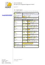
Display Cause

Possible solution

SP.Lo

Lower setpoint limit has 
been reached

Reduce limit (parameter 

SP.Lo

)

SP.Hi

Upper setpoint limit has 
been reached

Increase limit (parameter 

SP.Hi

)

 LOC

Parameter is locked

Unlock parameter, if necessary 
Parameter: 

 LOC

 on device configuration level

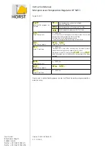
Er.Hi

Top range end has been 
exceeded, sensor defect

Check sensor and cable

Er.Lo

Bottom range end has been 
exceeded, sensor defect

Check sensor and cable
Check process value offset

Er.OP

Self tuning error

Quit error message by pressing key „ E“ .
Check self tuning conditions and restart.

Er.Sy
Err.0

System error

Quit error message by pressing key „ E“ .
Check all parameters.
If error message continues, please send the 
controller back to the manufacturer

Err.9

Internal Error

Communication error
Send the controller back to the manufacturer.

Er.Cn

Reference junction 
temperature error

The sensor for the reference junction measurement 
is located on the connection board. Check the cable.

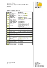
AL. Li

Temperature AL2 has been 
exceeded (over-temperature)

AL.Cu

Heating leakage current > 
0.3 A

A current is detected while the heating should be 
switched off.

OFF 

When starting the program 
controller: no ramp or dwell 
time is set.

Check program parameters. Set times for 

I.rA 


and/or 

I.t i 

 for the desired steps.

Strt

Program controller started

Only info message

hoL d

Program controller set to 
hold

Only info message

rESu

Program controller resumed

Only info message

StoP

Program controller stopped

Only info message

Version 1080/1.03 02/2018

471 11 400

Horst GmbH
Bitzenheimer Weg 10
D-64653 Lorsch
Telefon:  +49 (0) 6251 9626 0
Telefax: +49 (0) 6251 9626 96

Summary of Contents for HT MC11

Page 1: ...Output 0 10 V DC Option 8 6 4 Setpoint Adjustment 0 10 V DC Option 8 6 5 Potential Free Switching 8 7 Before First Operation 8 8 Parameter Description 9 8 1 Device Configuration Level 9 8 2 Alarm Conf...

Page 2: ...06 20 65 HT MC11 15 A KV Nominal current max 15 A Connection via cable glands Switching power at 230 V AC 3450 W 06 20 66 HT MC11 15 A plug socket 2 sensors Nominal current max 15 A Switching power a...

Page 3: ...re is required according to DIN EN 60519 2 DIN VDE 0721 part 2 Safety in electroheat installations Part 2 Particular requirements for resistance heating equipment 1 Description Due to high configurabi...

Page 4: ...In program controller mode keys are used for program functions instead of setpoint selection key E Confirmation and storage of the preselected values The display briefly shows a light chain for confi...

Page 5: ...tion level can be entered by pressing keys P and E for approx 1 second by pressing keys P and E longer the device configuration level can be reached Selection and adjustment of parameters as described...

Page 6: ...nly connect ohmic consumers to the regulator Permissible ambient temperature 0 40 C must be observed even in unfavor able circumstances Avoid direct sunlight Ensure sufficient ventilation The regulato...

Page 7: ...is switched off if the temperature exceeds the limit value The limit value is adjusted with parameter AL L see page 10 The supervision function must be activated by the parameter rEL C It is possible...

Page 8: ...range value max measuring range value of the selected control sensor 2 The analog output works in output ratio mode The output ratio is used e g for thyristor control see page 9 Out H Connection via c...

Page 9: ...752 F L8 C Thermocouple TC Fe CuNi L 0 800 C L8 F Thermocouple TC Fe CuNi L 32 1472 F J8 C Thermocouple TC Fe CuNi J 0 800 C J8 C Thermocouple TC Fe CuNi J 32 1472 F k1 C Thermocouple TC NiCr Ni K 0 8...

Page 10: ...lected switching cycle time is divided by 4 for slower and more uniform heating up Once the process value reaches the softstart setpoint the temperature is kept con stant for a preselectable duration...

Page 11: ...changed to manual mode using the last valid output ratio Manual mode is indicated with a leading H in the setpoint display followed by the output ratio The output ratio can be changed manually In foll...

Page 12: ...nt 2 is active Pr St Close ext contact start program controller Open ext contact stops program controller CL SH Close ext contact release self hold of temperature monitoring CLear Self Hold L0C Adjust...

Page 13: ...larm AL1 Temperature must be lower to activate alarm Over temperature alarm is not active AL1 OFF Both sided alarm limit alarm Temperature must be outside the selected range to activate alarm Both ala...

Page 14: ...lay time Alarm 1 OFF 1 1000 s rF A2 Alarm 1 configuration reference Alarm 2 AbS absolute bASE based on setpoint Cur Heating current monitoring works like absolute alarm rE A2 Relay action for alarm 2...

Page 15: ...tio limitation value Warning Output ratio limitation does not work during auto tune C Ly Max output ratio limitation cooling PID 0 100 See output ratio limitation heating Adjustment of Control Paramet...

Page 16: ...0 s optimal value for fast control loops 0 8 s Relay outputs cycle time 15 s The adjusted cycle time should be as long as possible to mini mize the wear of the relay contacts C P prop band P cooling P...

Page 17: ...starting the autotune algorithm Setpoint value must be higher than 5 of measuring range Sensor must not have a failure Softstart function must not be active OPt autotune OFF autotune not active on au...

Page 18: ...te OFF SP Lo SP Hi 500 Alarm active if actual process value is higher than alarm value rF A1 bASE based on setpoint OFF 1 100 K Alarm active if actual process value is higher than setpoint alarm value...

Page 19: ...hes Pressing again key sets program on hold Display shows hoLd for a short time ramp LED is on Resume program by pressing key again Display shows rESu ramp LED flashes Stop program by pressing key Dis...

Page 20: ...ion by setting value to 0 min I SP Step 1 Ramp setpoint SP Lo SP Hi Setpoint for this step I ti Step 1 Dwell time 0 6000 min The dwell time starts after the ramp has finished The con troller works usi...

Page 21: ...If error message continues please send the controller back to the manufacturer Err 9 Internal Error Communication error Send the controller back to the manufacturer Er Cn Reference junction temperatur...

Page 22: ...er 1 1000 If the range is exceeded the controller may be damaged Logic output Bist voltage signal 0 9 5 V DC max 10 mA short circuit proof Output relay AL1 Relay max 250 VAC max 2 A ohmic load Output...

Page 23: ......

Page 24: ......

Page 25: ......

Page 26: ......

Reviews: