background image


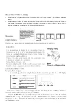
Master/Slave Fixture Linking 

1.


Connect the (male) 3 pin connector side of the DMX cable to the output (female) 3 pin connector of the first 

fixture. 

2.


Connect the end of the cable coming from the first fixture which will have a (female) 3 pin connector to the 

input connector of the next fixture consisting of a (male) 3 pin connector. Then proceed to connect from the 

output as stated above to the input of the following fixture and so on   


Mounting 

ORIENTATION 

This fixture may be mounted in any position provided there is adequate room for ventilation. 


4.OPERATING INSTRUCTIONS 

Navigating The Control panel 

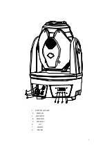
Access control panel functions using the four panel buttons located directly underneath the LCD Display. 


When  a  menu  function  is  selected.  The  display  will  show  immediately  the  first  available  option  for  the 

selected menu function, To select a menu item, press<ENTER> 

Press  the  <MODE/ESC>button  repeatedly  until  you  reach  the  desired  menu  function.  Use  the  <UP>and 

<DOWN> buttons to navigate the menu options. Press the 

ENTER>button to select the menu function currently 

displayed, or to enable a menu option. To return to the previous option or menu without changing the value. Press 

the <MODE/ESC>button. 

RIGGING 

It  is  important  never  to  obstruct  the  or  vents  pathway.  Mount  the 

fixture using ,a suitable “c” or

o” type clamp. Adjust the angle of the 

fixture  by  loosening  both  knobs  and  tilting  the  fixture.  Finding  the 

desired position, retighten both knobs. 

When  selecting  installation  location,  take  into  consideration  lamp 

replacement access and routine maintenance. 

Safety cables must always be used. 

Never mount in places where the fixture will be exposed to rain ,high 

humidity ,extreme temperature changes or restricted ventilation.. 


Summary of Contents for HS-LMS60R

Page 1: ...1 LED SPOT 60 MOVING HEAD USER MANUAL HS LMS60R ...

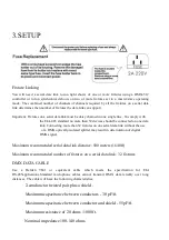
Page 2: ...nded for indoor use only To prevent risk of fire or shock do not expose fixture to rain or moisture Make sure there are no flammable materials close to the unit while operating The unit must be installed in a location with adequate ventilation at least 20in 50cm from adjacent surfaces Be sure that no ventilation slots are blocked Always disconnect from power source before servicing or replacing fu...

Page 3: ...3 1 SWlTCH ON OFF 2 DMX IN 3 DMX OUT 4 POWR IN 5 MUNE SC 6 UP 7 DOWN 8 ENTER ...

Page 4: ...UND ACTIVED ADDITONAL FEATURES COMPACT LIGHTWEIGHT LED DISPLAY MENU WITH INVERT RESET TO FACTORY SETTING OPTION PAN TILT INVERT OPTION FAN COOLED DMX Channel Summary 13 Channel mode Channel Function CH1 P A N CH2 T I L T CH3 O P E N S H U T T E R CH4 C O L O R W H E E L 7 C O L O R CH5 G O B O W H E E L 7 G O B O CH6 G O B O R O T A T I O N CH7 S P E E D F O R CH8 Dimming CH9 P A N 1 6 B I T CH1 0...

Page 5: ...k Connecting more than 32 fixtures on one serial data link without the use of a DMX optically isolated splitter may result in deterioration of digital DMX signal Maximum recommended serial data link distance 500 meters 1640ft Maximum recommended number of fixtures on a serial data link 32 fixtures DMX DATA CABLE Use a Belden 9841 or equivalent cable which meets the specification for EIA RS 485appl...

Page 6: ...output connector you will need to use a 5 pin to 3 pin adapter The chart below details a proper cable conversion 3 OIN TO 5 PIN CONVERSION CHART Conductor 3 Pin Female output 5Pin Male Input Ground Shield Pin1 Pin1 Tata signal Pin2 Pin2 Tata signal Pin3 Pin3 Do not use Do not use Do not use Setting up a DMX Serial Date Link 1 Connect the male 3 pin connector side of the DMX cable to the output fem...

Page 7: ...how immediately the first available option for the selected menu function To select a menu item press ENTER Press the MODE ESC button repeatedly until you reach the desired menu function Use the UP and DOWN buttons to navigate the menu options Press the ENTER button to select the menu function currently displayed or to enable a menu option To return to the previous option or menu without changing ...

Page 8: ...8 ...

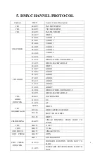
Page 9: ... 057 075 GOBO 3 076 093 GOBO 4 094 113 GOBO 5 114 132 GOBO 6 133 144 GOBO 7 145 208 WHOLE WHEEL FORWARD F S CH5 GOBO 209 255 WHEEL BACKWARD S F 000 011 NOT ROTATION 012 130 F S CH6 GOBO ROTATION 131 255 S F 000 011 WHITE 012 030 RESET AFTER 10 SECOND 031 250 SHUTTER S F WHITE CH7 STROBOFLASH 251 255 WHITE CH8 DIMMING 000 255 LINEAR DIMMING FROM LIGHT TO DARK CH9 000 255 X 16bit CH10 000 255 Y 16bi...

Page 10: ... size 520x430x420mm Net weight 11 kgs Gross weight 13kgs POWER Powersettings 220V50Hz 60Hz Fuse 2A220V Consumption 150W LIGHT SOURCE 1 X 60W WHITE COLOR LAMP LIFE 50 000Hrs CONTROL PROGRAMMING Data output locking3 pinXLRmalesocket Datainput locking3 pinXLRfemalesocket Protocols DMX 512 DMX channels 13 ...

Reviews: