26
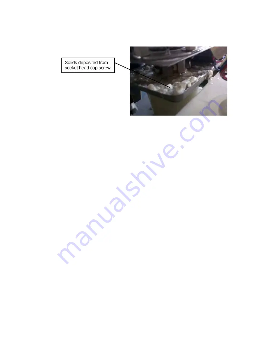
cap screw. The screw is provided with retaining and sealing functions, which may be
reduced by the load and vibration during a freeze cycle. Do not reuse a removed socket
head cap screw.
4. WATER CIRCUIT
[a] RESERVOIR (WATER TANK)
The Reservoir made of plastic maintains the water level necessary for ice production.
[b] FLOAT SWITCH
The Reservoir is provided with a plastic Float Switch to detect the water level. The floats
move up and down along with the water level and send ON/OFF signals to open/close the
Water Valve in order to maintain the proper water level.
If the proper water level cannot be resumed within a specific time after the Float Switch
sends an OFF signal, the icemaker will detect a low water condition and shut down. The
icemaker will automatically restart icemaking operation when the proper water level is
resumed.
If the Float Switch trips at the upper float level on startup and trips at the lower float level
(request for water supply) before the Compressor starts, the icemaker will display “E0” for a
water leak error and shut down.
If the Float Switch trips at the upper float level and does not trip at the lower float level, the
icemaker will display “E1” for a low ice production error and shut down.
If the Float Switch trips at both upper (fill) and lower (empty) float levels, the icemaker will
display “E2” for a switch contact error and shut down.
See “9. ERROR CODES” for details.
[c] CONTROL WATER VALVE
The Control Water Valve located above the Reservoir will open to supply water to the
Reservoir when the coil is energized. Despite the water pressure varying from 0.5 bar to 8
bar at the water supply inlet, the built-in flow controller maintains almost the same water
flow (24V AC).
Summary of Contents for FM-300AFE-HC
Page 7: ...3 2 DIMENSIONS CONNECTIONS a FM 481AGE HC FM 481AGE HCN ...
Page 8: ...4 b FM 300AFE HC FM 300AFE HCN ...
Page 9: ...5 3 SPECIFICATIONS a FM 481AGE HC ...
Page 10: ...6 b FM 481AGE HCN ...
Page 11: ...7 c FM 300AFE HC ...
Page 12: ...8 d FM 300AFE HCN ...
Page 14: ...10 Drier Ice Chute Pressure Switch ...
Page 23: ...19 b FM 300AFE HC FM 300AFE HCN Pressure Switch Cut out 22 6 1 5 0 bar Cut in 15 7 1 5 bar ...
Page 24: ...20 2 WIRING DIAGRAM a WIRING DIAGRAM FM 481AGE HC FM 481AGE HCN ...
Page 25: ...21 FM 300AFE HC FM 300AFE HCN ...
Page 26: ...22 b CONTROL BOX LAYOUT FM 481AGE HC FM 481AGE HCN ...
Page 27: ...23 FM 300AFE HC FM 300AFE HCN ...
Page 35: ...31 FM 300AFE HC FM 300AFE HCN ...
Page 36: ...32 ...
Page 37: ...33 c SEQUENCE FM 481AGE HC FM 481AGE HCN 1 Startup Water Supply ...
Page 39: ...35 FM 481AGE HC FM 481AGE HCN 3 Startup Ice production starts ...
Page 40: ...36 FM 481AGE HC FM 481AGE HCN 4 Normal Operation Bin Control ...
Page 41: ...37 FM 481AGE HC FM 481AGE HCN 5 Shutdown Compressor stops 5 min ...
Page 42: ...38 FM 481AGE HC FM 481AGE HCN 6 Shutdown Drain ...
Page 43: ...39 FM 300AFE HC FM 300AFE HCN 1 Startup Water Supply ...
Page 45: ...41 FM 300AFE HC FM 300AFE HCN 3 Startup Ice production starts ...
Page 46: ...42 FM 300AFE HC FM 300AFE HCN 4 Normal Operation Bin Control ...
Page 47: ...43 FM 300AFE HC FM 300AFE HCN 5 Shutdown Compressor stops 5 min ...
Page 48: ...44 FM 300AFE HC FM 300AFE HCN 6 Shutdown Drain ...


