12
II. MAINTENANCE AND CLEANING INSTRUCTIONS
IMPORTANT
1. This icemaker must be maintained individually, referring to the instruction manual
and labels provided with the icemaker.
2. To achieve optimum icemaker performance, the following parts need periodic
inspection and maintenance:
Extruding head (upper bearing)
Housing (lower bearing)
Mechanical
seal
These parts should be inspected after two years from installation or 10,000 hours of
operation, whichever comes first, and once a year thereafter. Their service life,
however, depends on water quality and environment. More frequent inspection and
maintenance are recommended in bad or severe water conditions.
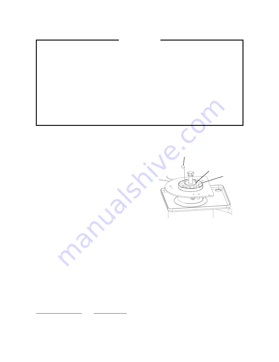
1. EXTRUDING HEAD (UPPER BEARING), HOUSING (LOWER BEARING)
These parts should be replaced if a diametrical gap
of more than 0.5 mm is found when at least three
spots are checked by changing the direction of the
auger on each bearing.
It depends on the water quality and conditions, but
normally the bearings should be checked for wear
after a total of 8,000 - 10,000 hour operation from
installation date.
Note: The clearance between the auger blades
and the evaporator interior is 0.4 - 0.5 mm. If
the bearings and rotating parts are worn out
to create a larger clearance, the evaporator
interior may be damaged. (The diameters
differ by 0.8 - 1.0 mm.)
If the auger surfaces against which the bearings contact are no longer smooth or
show any burrs or abrasions during the above inspection, replace the auger. The
sealing bolt must be tightened equally to torque of 784N
·
cm
±
10%.
2. MECHANICAL SEAL
The mechanical seal prevents water leaks from between the auger and the housing bearing
and gradually wears out to reduce its watertightness. Check the amount of water leakage
from the drain pipe located at the side of the gear case to determine the necessity of
replacement.
Total operation time
Water leakage
3,000 hours
0.1 mL/h
10,000 hours
0.5 mL/h
For reference only
(May differ from actual design)
Auger
0.5 mm Round Stock
or Pin Gauge
Extruding
Head
Summary of Contents for FM-300AKE-HC
Page 4: ...1 I SPECIFICATIONS 1 DIMENSIONS SPECIFICATIONS a FM 300AKE HC Auxiliary code D 0 or earlier ...
Page 5: ...2 b FM 300AKE HC Auxiliary code D 1 or later ...
Page 6: ...3 c FM 300AKE HCN Auxiliary code D 0 or earlier ...
Page 7: ...4 d FM 300AKE HCN Auxiliary code D 1 or later ...
Page 8: ...5 e FM 480AKE HC Auxiliary code D 0 or earlier ...
Page 9: ...6 f FM 480AKE HC Auxiliary code D 1 or later ...
Page 10: ...7 g FM 480AKE HCN Auxiliary code D 0 or earlier ...
Page 11: ...8 h FM 480AKE HCN Auxiliary code D 1 or later ...
Page 21: ...18 2 WIRING DIAGRAM a WIRING DIAGRAM FM 300AKE HC N Auxiliary code D 0 or earlier ...
Page 22: ...19 FM 300AKE HC N Auxiliary code D 1 or later ...
Page 23: ...20 FM 480AKE HC N Auxiliary code D 0 or earlier ...
Page 24: ...21 FM 480AKE HC N Auxiliary code D 1 or later ...
Page 33: ...30 b TIMING CHART ...


