ENGLISH
3
5. Allow 15 cm clearance at rear and sides
for proper air circulation and ease of
maintenance and/or service should they be
required. Allow 60 cm clearance on top to
allow for removal of the Auger.
6. This appliance is not suitable for installation
in an area where a water jet could be used
and where dripping is not allowed.
7. Do not place anything on top of the icemaker.
3. INSTALLATION
* Incorrect installation can cause harm to people,
animals or things, for which the manufacturer
cannot be held responsible.
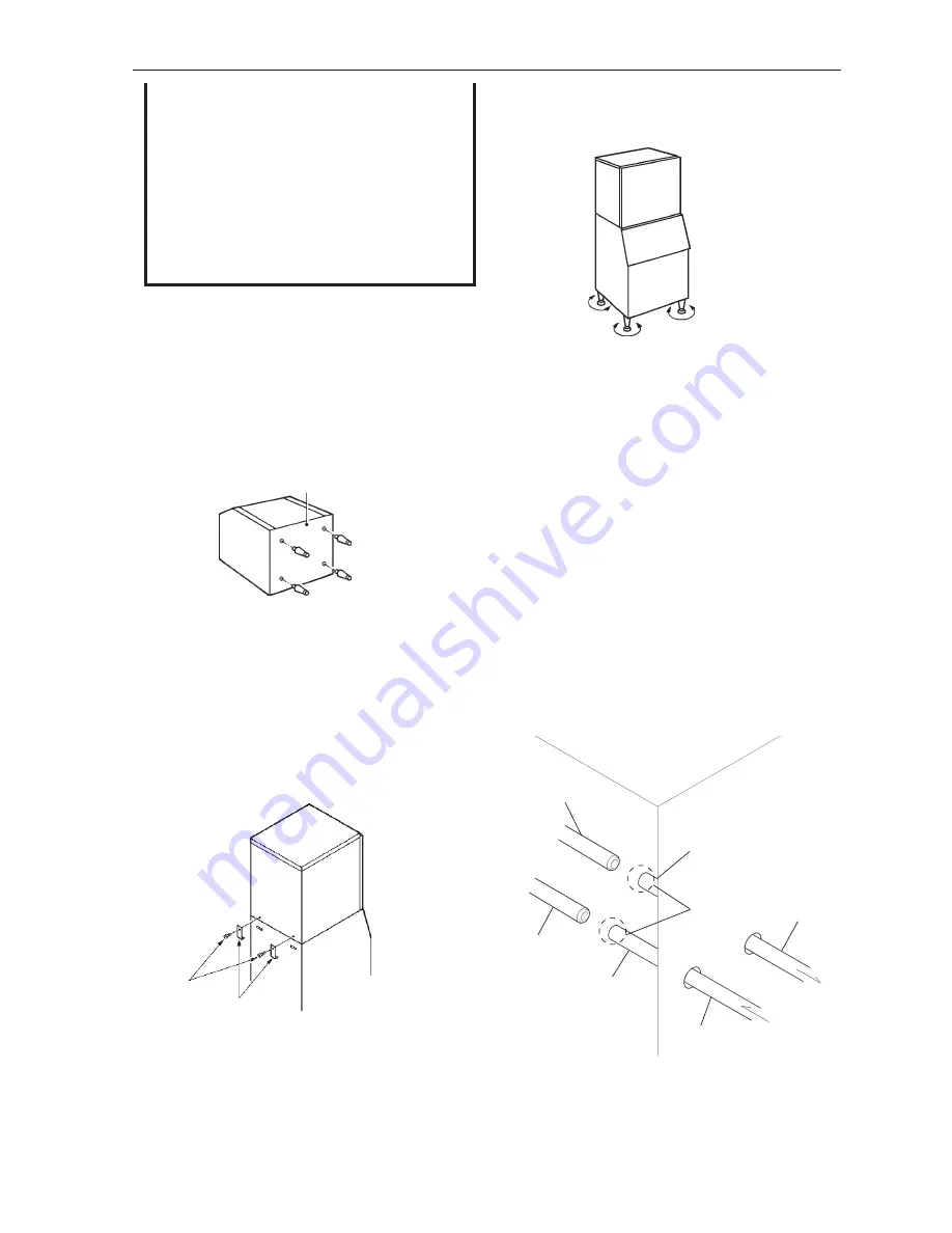
1) Fully screw in the four legs provided (bin
accessory) into the Storage Bin underside. See
Fig. 3.
2) Position the Storage Bin in the selected
permanent site.
3) Place the icemaker on top of the Storage Bin by
holding the bottom.
4) Secure the icemaker to the Storage Bin, by
using the two mounting brackets and two bolts
provided. See Fig. 4.
7) The icemaker must be connected to the liquid
and suction lines of the compressor system using
two copper tubes of sufficient sizes directed to
the rear of the icemaker for connection to the pre-
fitted internal copper tubes. Both tubes should be
insulated separately.
Note: 1. The sizes of the interconnecting pipes
between the icemaker and the compressor
system should be 1/4” OD for the liquid
line and 1/2” for the suction line up to a
maximum of 20 m (assuming a straight
run). For each 90° bend, add an equivalent
0.5 m to the overall pipe length (E.g. 20 m
straight pipe + four 90° bends = equivalent
22 m of straight pipe). Equivalent pipe
lengths that exceed 20 m should be
increased in size to 3/8” OD liquid line and
5/8” OD suction line.
6) Adjust the four legs on the bottom (adjustable
from 0 to 25.4 mm) to have the icemaker perfectly
horizontal. Use the spirit level. See Fig. 5.
Bottom Plate
Adjustable Legs
Fig. 3
Fig. 5
Adjust legs
Fig. 4
Icemaker
Mounting
Bracket
Bin
Bolt
Fig. 6
1/2” ID
Suction Line
Liquid Line
1/4” ID
Expand
Suction Line
Liquid Line
Icemaker
5) Seal the seam between the icemaker and the
Storage Bin with food grade sealant.


