
13
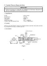
3. Evacuation
1) Attach a vacuum pump to the system. Be sure to connect the charging hoses to both high
and low-side refrigerant piercing valves.
IMPORTANT
The vacuum level and vacuum pump may be the same as those for current refrigerants.
However, the rubber hose and gauge manifold to be used for evacuation and refrigerant
charge should be exclusively for POE oils.
2) Turn on the vacuum pump, then open the gauge manifold valves. Never allow the oil in
the vacuum pump to flow backwards.
3) Allow the vacuum pump to pull down to a 760 mmHg vacuum. Evacuating period depends
on pump capacity.
4) Close the low-side valve and high-side valve on the gauge manifold.
5) Disconnect the gauge manifold hose from the vacuum pump and attach it to refrigerant
service cylinder. Remember to loosen the connection and purge the air from the hose. For
the required refrigerant charge, see the nameplate.
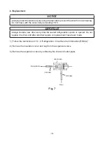
4. Recharge
6) R600a can be charged in either the liquid or vapor state. Liquid charge is preferred. If
refrigerant charging is done in the liquid state, place the service cylinder on the scales;
if
the service cylinder is not equipped with a dip tube, invert the service cylinder, then
place it on the scales.
Open the high-side valve on the gauge manifold.
7) Allow the system to charge with liquid until the proper charge weight is met.
8) Close the high-side valve on the gauge manifold. If charging is complete, skip to step 10.
9) If necessary, add any remaining charge to the system through the low-side.
NOTICE!
To prevent compressor damage, use a throttling valve or liquid dispensing device
to add the remaining liquid charge through the low-side refrigerant access valve
with the compressor running.
Close the refrigerant cylinder valve and let the low-
side refrigerant equalize to the system, then close the low-side manifold gauge. Move
the power switch (earth leakage circuit breaker) to the “OFF” position, then unplug the
appliance from the electrical outlet.
10) Pinch off (crimp down) the process tubes just below the piercing valves.
11) Remove the piercing valves. Cut the process tubes to remove the piercing valve holes
then braze the process tubes closed. Note: Be sure there is no refrigerant leak before
brazing.
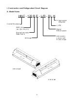
Summary of Contents for HNC-120BE-L-BH
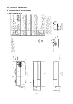
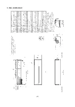
Page 22: ...21 VI Technical Information A Dimensions Specifications 1 HNC 120BE L BLH...
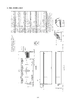
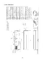
Page 23: ...22 2 HNC 150BE L BLH...
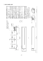
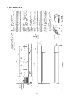
Page 24: ...23 3 HNC 180BE L BLH...
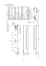
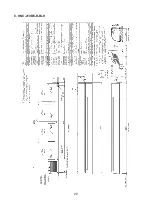
Page 25: ...24 4 HNC 210BE L BLH...
Page 26: ...25 5 HNC 120BE R BLH...
Page 27: ...26 6 HNC 150BE R BLH...
Page 28: ...27 7 HNC 180BE R BLH...
Page 29: ...28 8 HNC 210BE R BLH...
Page 30: ...29 9 HNC 120BE L BH...
Page 31: ...30 10 HNC 150BE L BH...
Page 32: ...31 11 HNC 180BE L BH...
Page 33: ...32 12 HNC 210BE L BH...
Page 34: ...33 13 HNC 120BE R BH...
Page 35: ...34 14 HNC 150BE R BH...
Page 36: ...35 15 HNC 180BE R BH...
Page 37: ...36 16 HNC 210BE R BH...