background image

16

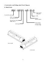
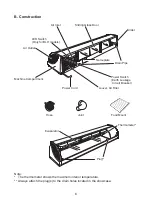
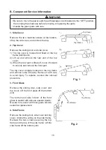
5. Center Frame (Except HNC-120 Type)

Remove the two flat head machine screws (black) 

securing the center frame to the rear and the two 

machine screws securing the center frame to the top 

frame. Tilt the center frame and release it from the 

joint.

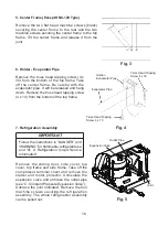
6. Holder - Evaporator Pipe

Remove the truss head tapping screw (4 x 

30) from the bottom of the top frame. Take 

off the center frame. Be careful with the 

evaporator pipe. It will be released and hang 

down. Remove the truss head tapping screw 

(4 x 10) from the bottom of the top frame.

7. Refrigeration Assembly

IMPORTANT

Follow the instructions in “DANGER” and 

“WARNING” for flammable  refrigerant use  

and “III. A. Refrigeration Circuit Service 

Information”. 

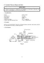
Remove the sliding door, side cover, top 

cover,  top  frame  and  side  frame. Take  off  the 

compressor terminal cover and remove the 

starter and motor protector. Uninsulate the 

expansion valve and unbraze the outlet pipe  

(see “C. Constant Pressure Expansion Valve”).

Unbraze the joint indicated. Remove the four 

machine screws securing the refrigeration 

assembly. The whole refrigeration assembly 

can be pulled out.

Fig. 3

Fig. 4

Truss Head Tapping 

Screw 4 x 30

Truss Head Tapping 

Screw 4 x 10

Holder - 

Evaporator Pipe

Evaporator Pipe

Fig. 5

Outlet Pipe

Joint

Expansion Valve

Summary of Contents for HNC-120BE-L-BH

Page 1: ...HNC 120BE L R BLH HNC 150BE L R BLH HNC 180BE L R BLH HNC 210BE L R BLH HNC 120BE L R BH HNC 150BE L R BH HNC 180BE L R BH HNC 210BE L R BH COUNTER SHOWCASE SERVICE MANUAL S051 1106 051421...

Page 2: ...ion 2 I Construction and Refrigeration Circuit Diagram 5 A Model Name 5 B Construction 6 C Refrigeration Circuit Diagram 7 II Operating Instructions and Service Diagnosis 8 A Operating Instructions 8...

Page 3: ...and care of the appliance DANGER Risk of Fire or Explosion Flammable Refrigerant Used Follow handling instructions carefully in compliance with national or local regulations Do not use mechanical dev...

Page 4: ...mponent failure This could lead to heat generation or fire Do not use an extension cord Do not use an appliance with a damaged power cord The power cord should not be altered jerked bundled weighed do...

Page 5: ...will raise the interior temperature and could deteriorate other foods in the unit or overload the appliance Food display and handling must comply with applicable codes and regulations All foods should...

Page 6: ...m A Model Name HNC 120 B E L R B L H H Hydrocarbon refrigerant Counter Showcase L LED Width cm 120 150 180 210 Exterior B Black plastic Development Order Starts from A Unit Location HE Model L Unit on...

Page 7: ...s Air Outlet Nameplate Power Switch Earth Leakage Circuit Breaker Louver Air Filter Evaporator Power Cord Machine Compartment Plug Thermometer Food Mount Joint Hose Note The thermometer shows the maxi...

Page 8: ...7 Refrigerant R600a Heat Exchanger Drier Expansion Valve Evaporator Upper Evaporator Lower Fan Motor Compressor C Refrigeration Circuit Diagram Condenser...

Page 9: ...en them too frequently The interior temperature may rise resulting in food deterioration 4 Do not pack the showcase with foods The cooling performance may reduce resulting in food deterioration 5 The...

Page 10: ...1 Foods have been stored from the previous day 1 2 Instruct the user on characteristics and proper use of the showcase 2 Foods have been stored for a long time 4 Condensation formed 1 Exterior Relati...

Page 11: ...propriate personal protective equipment PPE when servicing the appliance Technician must utilize a combustible gas leak detector at all times Notify everyone in the immediate area that you are working...

Page 12: ...l after all other repair or replacement has been made Install the new drier with the arrow on the drier in the direction of the refrigerant flow When brazing protect the drier by using a wet cloth to...

Page 13: ...ant vapor before brazing 1 Braze repair replace damaged component or fitting 2 Purge with nitrogen gas for 2 min Then braze all fittings while purging with nitrogen gas flowing at a pressure of 0 02 t...

Page 14: ...t charging is done in the liquid state place the service cylinder on the scales if the service cylinder is not equipped with a dip tube invert the service cylinder then place it on the scales Open the...

Page 15: ...14 12 Use a combustible gas leak detector or soap bubbles to check for leaks again 13 Place red sleeves over the process tubes 14 Plug the appliance back into the electrical outlet...

Page 16: ...forward to unhook and remove the front part The top cover is tightly hooked on the top frame and will not come off easily Remove it with care to avoid injury To replace reverse the removal procedure...

Page 17: ...7 Refrigeration Assembly IMPORTANT Follow the instructions in DANGER and WARNING for flammable refrigerant use and III A Refrigeration Circuit Service Information Remove the sliding door side cover t...

Page 18: ...t Number P04945 01 Refrigerant R600a Adjustment Range 0 01 0 29MPaG Pressure Rise by Adjusting Screw 0 039 0 049MPa tum 2 Function When the low side pressure drops the constant pressure expansion valv...

Page 19: ...very time the sealed refrigeration system is opened Do not replace the drier until after all other repairs or replacement have been made 1 Follow the instructions in III A Refrigeration Circuit Servic...

Page 20: ...n getting injured NOTICE When preparing the appliance for long storage clean the appliance See III Maintenance and Cleaning Instructions in the instruction manual for details 1 Before shutting down th...

Page 21: ...refrigerant tubing follow handling instructions carefully Dispose of properly in accordance with national or local regulations WARNING When preparing the appliance for disposal remove the doors to re...

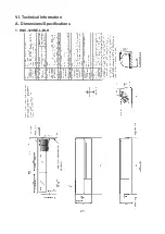
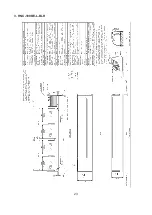
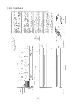
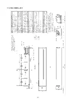
Page 22: ...21 VI Technical Information A Dimensions Specifications 1 HNC 120BE L BLH...

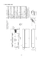
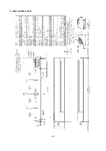
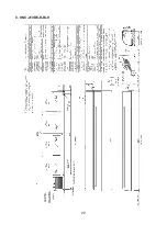
Page 23: ...22 2 HNC 150BE L BLH...

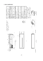
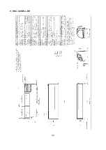
Page 24: ...23 3 HNC 180BE L BLH...

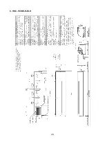
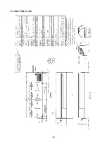
Page 25: ...24 4 HNC 210BE L BLH...

Page 26: ...25 5 HNC 120BE R BLH...

Page 27: ...26 6 HNC 150BE R BLH...

Page 28: ...27 7 HNC 180BE R BLH...

Page 29: ...28 8 HNC 210BE R BLH...

Page 30: ...29 9 HNC 120BE L BH...

Page 31: ...30 10 HNC 150BE L BH...

Page 32: ...31 11 HNC 180BE L BH...

Page 33: ...32 12 HNC 210BE L BH...

Page 34: ...33 13 HNC 120BE R BH...

Page 35: ...34 14 HNC 150BE R BH...

Page 36: ...35 15 HNC 180BE R BH...

Page 37: ...36 16 HNC 210BE R BH...

Page 38: ...ELB Earth Leakage Circuit Breaker SR Start Relay CM Compressor SC Start Capacitor OL Overload Relay FM Fan Motor CB Switching Regulator S LED Switch CB1 3 LED Board HNC 120BE CB1 4 LED Board HNC 150BE...

Reviews: