35
3. FAN MOTOR CONTROL - 240ME/M2E ONLY
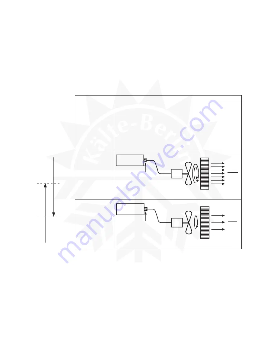
The Condenser Fan Motor rotates at two speeds. The Motor is operated by Relay X6 which
is in turn controlled by the Bimetal Thermostat which is attached to the Control Box. When the
Relay is energised (Thermostat contacts closed), the Motor operates at approximately half
speed. When the Relay is de-energised (Thermostat contacts open), the Motor operates at
full speed.
Half speed = 11±3°C
Full speed = 21±3°C (1272 R.P.M.)
Construction &
Features
High Temp.
Condition
(RT Min. 10°C)
Low Temp.
Condition
(RT Max. 10°C)
1) Employs dual-speed fan motor control.
2) Bimetal thermostat slows down fan motor rotation (less
airflow) at low temperatures to prevent excessive
condensation.
3) ±5% of new refrigerant charge has been evaluated at
RT 1 - 40°C.
4) Reduced refrigerant charge (less than half) solves
troubles with remaining refrigerant at low temperatures.
Control Box
Bimetal Thermostat
(21±3°C)
FM
Rotating rapidly
(50/60Hz: 1272/1345 r/min)
Pressure: 18 - 27kg/cm
2
G
Condenser
Much
airflow
Control Box
Bimetal Thermostat
(11±3°C)
FM
Rotating rapidly
(50/60Hz: 748/678 r/min)
Pressure: 14 - 18kg/cm
2
G
Condenser
Little
airflow
RT: High
RT: Low
Rotating slowly (748r/min)
Rotating rapidly (1272r/min)
21±3°C
11±3°C
Summary of Contents for IM-100
Page 5: ...1 I SPECIFICATIONS 1 DIMENSIONS CONNECTIONS a IM 25LE Air cooled ...
Page 6: ...2 b IM 25CLE Air cooled Until March 2000 production Auxiliary Code K 1 ...
Page 7: ...3 c IM 21CLE IM 25CLE IM 30CLE Air cooled From April 2000 production Auxiliary Code K 2 ...
Page 8: ...4 d IM 45LE Air cooled ...
Page 9: ...5 e IM 45CLE 25 Air cooled ...
Page 10: ...6 f IM 65LE Air cooled ...
Page 11: ...7 g IM 100LE IM 130LE IM 130ME Air cooled ...
Page 12: ...8 h IM 100CLE Air cooled ...
Page 13: ...9 i IM 160ME Air cooled ...
Page 14: ...10 j IM 240ME Air cooled ...
Page 15: ...11 k IM 240M2E Air cooled ...
Page 16: ...12 l IM 25WLE IM 30WLE Water cooled ...
Page 17: ...13 m IM 45WLE Water cooled ...
Page 18: ...14 n IM 65WLE Water cooled ...
Page 19: ...15 o IM 100WLE IM 130WLE IM 130WME Water cooled ...
Page 20: ...16 p IM 240WME Water cooled ...
Page 21: ...17 q IM 240WM2E Water cooled ...
Page 70: ...66 2 WIRING DIAGRAM a IM 21CLE IM 25LE IM 25CLE IM 30CLE IM 25WLE IM 30WLE ...
Page 71: ...67 b IM 25L IM 25CL IM 25WL ...
Page 72: ...68 c IM 45LE IM 45CLE 25 IM 45WLE ...
Page 73: ...69 d IM 65LE IM 65WLE ...
Page 74: ...70 e IM 65L IM 65WL ...
Page 76: ...72 g IM 130LE IM 130WLE Note The Washing Switch is provided only after the Auxiliary Code H 0 ...
Page 78: ...74 i IM 130ME IM 130WME Note The Washing Switch is provided only after the Auxiliary Code H 0 ...
Page 80: ...76 k IM 160ME ...
Page 81: ...77 l IM 240ME IM 240WME ...
Page 82: ...78 m IM 240M2E IM 240WM2E ...
Page 120: ...116 Fig 30 ...


