45
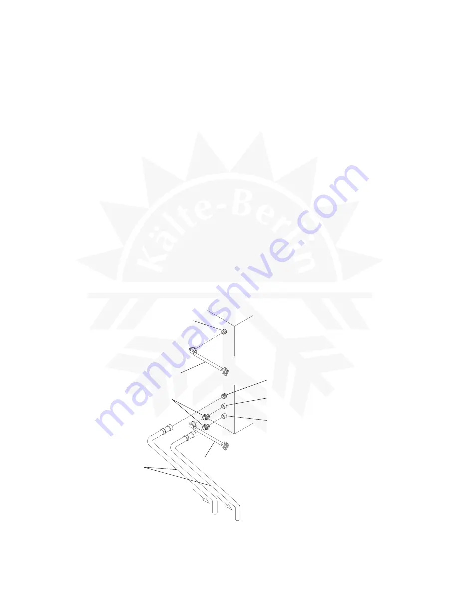
Fig. 11
Potable Water
Inlet G3/4
Inlet Hose
Outlet Hose
Inlet Hose
Drain Outlet R3/4
Cooling Water
Inlet Rc1/2
Cooling Water
Outlet Rc1/2
1/2-3/4 Nipple
* When adjusting the Water Regulator to increase the pressure or to lower the temperature of
the cooling water, do not exceed the following ranges to prevent erosion in the water circuit:
Flow Speed:
2 m/sec or less
Flow Rate:
5.9 lit/min or less
* Water flow can be reduced down to 60%. The differential between the inlet and outlet water
temperatures will increase (to 8°C with 60% water flow), but the cooling capacity will
decrease. Be sure to keep enough capacity in summer.
Note: When installing a Flow Control Valve as shown in Fig. 10, the condition at the Cooling
Water Inlet should not exceed the following ranges:
Water Temperature:
30°C or less
Water Pressure:
0.5 bar or more
Flow Rate:
8 - 10 lit/min
[b] Connections according to regulations other than WRC by utilising accessory
hoses (Fig. 11)
1) Follow the instructions from 1) to 4) in [a] above.
2) For Condenser connections, use supplied accessory hoses and make the same
connections as 1) to 3) in [a] above to the free end of 1/2-3/4 nipples as indicated (Fig.
11).
Summary of Contents for IM-100
Page 5: ...1 I SPECIFICATIONS 1 DIMENSIONS CONNECTIONS a IM 25LE Air cooled ...
Page 6: ...2 b IM 25CLE Air cooled Until March 2000 production Auxiliary Code K 1 ...
Page 7: ...3 c IM 21CLE IM 25CLE IM 30CLE Air cooled From April 2000 production Auxiliary Code K 2 ...
Page 8: ...4 d IM 45LE Air cooled ...
Page 9: ...5 e IM 45CLE 25 Air cooled ...
Page 10: ...6 f IM 65LE Air cooled ...
Page 11: ...7 g IM 100LE IM 130LE IM 130ME Air cooled ...
Page 12: ...8 h IM 100CLE Air cooled ...
Page 13: ...9 i IM 160ME Air cooled ...
Page 14: ...10 j IM 240ME Air cooled ...
Page 15: ...11 k IM 240M2E Air cooled ...
Page 16: ...12 l IM 25WLE IM 30WLE Water cooled ...
Page 17: ...13 m IM 45WLE Water cooled ...
Page 18: ...14 n IM 65WLE Water cooled ...
Page 19: ...15 o IM 100WLE IM 130WLE IM 130WME Water cooled ...
Page 20: ...16 p IM 240WME Water cooled ...
Page 21: ...17 q IM 240WM2E Water cooled ...
Page 70: ...66 2 WIRING DIAGRAM a IM 21CLE IM 25LE IM 25CLE IM 30CLE IM 25WLE IM 30WLE ...
Page 71: ...67 b IM 25L IM 25CL IM 25WL ...
Page 72: ...68 c IM 45LE IM 45CLE 25 IM 45WLE ...
Page 73: ...69 d IM 65LE IM 65WLE ...
Page 74: ...70 e IM 65L IM 65WL ...
Page 76: ...72 g IM 130LE IM 130WLE Note The Washing Switch is provided only after the Auxiliary Code H 0 ...
Page 78: ...74 i IM 130ME IM 130WME Note The Washing Switch is provided only after the Auxiliary Code H 0 ...
Page 80: ...76 k IM 160ME ...
Page 81: ...77 l IM 240ME IM 240WME ...
Page 82: ...78 m IM 240M2E IM 240WM2E ...
Page 120: ...116 Fig 30 ...


